Table of Contents
- Key takeaways
- How do engineers calculate dead load in PEB design?
- How is wind load calculated for a pre-engineered building?
- How do engineers determine seismic load in PEB design?
- Which load combinations apply in PEB design?
- What design considerations follow the load calculations?
- How do accurate loads affect members, connections, and foundations?
- Why does detailing accuracy matter for load paths?
- Wrapping up
- Frequently asked questions
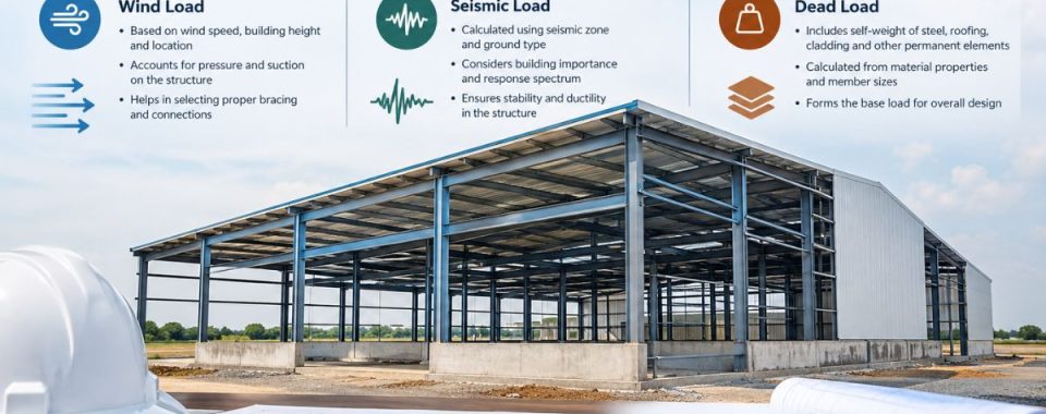
Engineers work out dead load by adding up the weight of the structure and its permanent attachments. Wind load comes from applying ASCE 7 pressures for the site to the roof and walls. Seismic load comes from estimating the lateral force the building’s mass attracts during ground shaking. All three matter in PEB design because the frames are light and optimized, with little spare capacity. A small error in any of them can change frame depth, connection capacity, anchor rods, and foundation size.
Key takeaways
- Dead load comes from known weights. Wind and seismic loads are estimates built from site conditions, building geometry, and code rules.
- In the USA, ASCE 7 sets the wind and seismic criteria. The MBMA Metal Building Systems Manual covers PEB-specific practice.
- Every member and connection is checked against the worst load combination, and that check sets its size.
- Design loads only protect the building if the detailing and fabrication drawings carry them through.
How do engineers calculate dead load in PEB design?
Dead load is the most predictable of the three. It covers the weight of:
- Primary frames- columns, rafters, and base plates
- Secondary members- purlins, girts, and eave struts
- Roof and wall sheeting, insulation, and trim
- Bracing, connections, and fasteners
Collateral load covers items that hang from or sit on the building but are not part of the metal building system. Sprinklers, lighting, ductwork, ceilings, and rooftop units are the usual examples. Solar panels show up more often now and need their own allowance.
However, early in design, engineers use allowances taken from similar buildings. As the design firms up, they replace those with actual member weights and the manufacturer’s data for cladding and equipment.
A PEB’s dead load is small next to wind uplift, so it often helps the building. That is why the reduced dead load factor appears in the uplift and overturning combinations.
How is wind load calculated for a pre-engineered building?
For most PEBs in the USA, wind design follows ASCE 7, adopted through the International Building Code (IBC). The engineer works out pressures for two separate systems:
- The main wind force resisting system, meaning the frames and bracing that carry wind down to the foundation.
- Components and cladding, meaning purlins, girts, sheeting, and their fasteners, which see higher local pressures.
What factors change the wind pressure?
- Basic wind speed, which depends on location and the building’s risk category.
- Exposure category. Open terrain produces higher pressures than suburban or wooded surroundings.
- Topography. Hills, ridges, and escarpments can speed up the wind.
- Enclosure classification: enclosed, partially enclosed, or open. If a large door fails or is left open, an enclosed building can behave as partially enclosed, and that raises internal pressure.
- Geometry, including mean roof height, roof slope, building width and length, and overhangs.
- Pressure zones. Roof corners, edges, and end walls take higher pressures than the middle of the roof.
Therefore, on low-slope PEBs, wind often governs. The roof sees suction, and the walls take pressure from both directions, which can reverse the forces in rafters and columns.
How do engineers determine seismic load in PEB design?
Seismic design also follows ASCE 7. The steps run roughly in this order:
- Determine the risk category from the building’s use.
- Find the mapped spectral accelerations for the site.
- Classify the soil (site class) and adjust the accelerations.
- Assign a Seismic Design Category.
- Select the seismic force resisting system and its response modification coefficient, R.
- Calculate the seismic weight and base shear.
In the equivalent lateral force method, base shear is V = Cs × W. W is the effective seismic weight, and Cs depends on the design spectral acceleration, R, and the importance factor. Seismic weight includes dead load plus some other items, such as permanent equipment and, in certain cases, part of the snow load.
Because PEBs are light, seismic loads are often lower than wind loads in low-seismic regions. That can change in high seismic zones, or when the building carries mezzanines, heavy equipment, cranes, or concrete or masonry walls.
Moreover, PEBs use systems with low R values, but the engineer has to confirm what the code allows for the chosen frame type and Seismic Design Category. Roof bracing and diaphragm behavior also need attention, since they deliver seismic forces to the lateral system.
Which load combinations apply in PEB design?
Codes require engineers to check loads in combination, and the worst case for each member sets its size. The table below lists common strength design (LRFD) combinations from ASCE 7.
| Combination | What it checks |
| 1.2D + 1.6(Lr or S) + 0.5W | Gravity-driven cases, roof live or snow load |
| 1.2D + 1.0W + L + 0.5(Lr or S) | Wind acting with gravity |
| 0.9D + 1.0W | Wind uplift and load reversal |
| 1.2D + 1.0E + L + 0.2S | Seismic acting with gravity |
| 0.9D + 1.0E | Seismic overturning and uplift |
D is dead load, L is live load, Lr is roof live load, S is snow load, W is wind load, and E is seismic load. Allowable stress design combinations use different factors. The engineer applies whichever set belongs to the code edition the local jurisdiction has adopted. The table is a summary and does not replace the code.
Furthermore, the 0.9D combinations deserve extra care. A PEB can weigh very little compared with the uplift it may see, so these cases often control anchor rods and foundation uplift resistance.
What design considerations follow the load calculations?
Once the loads are known, engineers still have several checks to make:
- Load path- Every load has to travel from where it lands, through cladding, purlins, frames, connections, and anchor rods, into the foundation with no gap along the way.
- Drift and deflection- Lateral movement under wind and seismic loads must stay within limits set by the project, the code, and MBMA guidance, especially where walls carry brittle finishes or a crane runway is attached.
- Member stability- Bracing and flange restraint matter most where wind or seismic loads reverse which side of a member is in compression.
- Special loads- Cranes, mezzanines, rooftop units, solar arrays, and planned expansions should be identified early because they change both dead load and lateral demand.
- Local amendments- Some jurisdictions modify wind, snow, or seismic requirements, so the design basis should be confirmed for the project location.
How do accurate loads affect members, connections, and foundations?
For members, primary frames use tapered sections, with web depth and flange size matched to the forces along the length. An overestimated load makes the steel heavier than it needs to be. An underestimated one can leave a rafter or column short of capacity. Purlin and girt spacing, lap lengths, and bracing all depend on the same load numbers.
Connections are where load errors show up first, because they have less reserve than the members they join. Moment connections at the knee and ridge depend on bolt size, end plate thickness, and stiffeners, all driven by the design forces. Brace connections and clips carry the lateral loads. Steel detailing services in USA check each of these against the connection forces before anything reaches the shop.
Foundations need a reaction table for each column, with vertical, horizontal, and uplift forces for every load case, not only the maximum downward load. In a light PEB, uplift, overturning, and sliding often control the footing and pier design. Anchor rod size, embedment, and base plate details must match those reactions, and the detailer works from the same reaction data when drawing the base plates.
Why does detailing accuracy matter for load paths?
The engineer’s calculations set the required capacities. The detailer turns them into what the shop builds and the crew erects. If a plate thickness, bolt count, weld size, or hole location differs from the design, the connection no longer matches the calculated load path.
That is why fabricators and erectors value close coordination between design and detailing. Reliable structural steel detailing services in USA projects convert the engineer’s connection forces, member sizes, and bracing layout into drawings the shop can build without having to interpret them. Complete steel fabrication drawings services in the USA also show anchor rod layouts, base plate details, and bracing connections so they line up with the foundation design.
Detailing also catches conflicts before fabrication, such as bracing that runs into an opening or clips that miss the purlin lines. Shop drawings services in the USA that carry piece marks, bolt details, and weld symbols let the shop and the field crew build what the engineer intended. At 12 Meter Engineering, the aim is to keep the drawings consistent with the design intent from the first submittal to the final revision.
Wrapping up
Dead, wind, and seismic loads are the starting point of every PEB design. Dead load is calculated from known weights. Wind and seismic loads are estimated under ASCE 7 from the site, the building geometry, and the risk category. The governing load combinations then set the size of each member, connection, and foundation element.
A good design also depends on what happens after the calculations. Load paths have to stay continuous, drift has to be controlled, and unusual loads need to be identified early. The design intent then has to survive fabrication and erection. That is where structural steel detailing services in the USA and clear steel fabrication drawings services in USA earn their place, because a connection built to the wrong detail no longer carries the load the engineer calculated.
Before a PEB project moves forward, confirm the code edition, the local amendments, and the design loads with the engineer of record.
Frequently asked questions
Dead load is the permanent weight of the structure and its fixed items. Live load is temporary or movable, such as people, maintenance loads, or roof live load.
ASCE 7 sets the wind criteria and is adopted through the International Building Code. Which edition applies depends on what the local jurisdiction has adopted.
Wind often governs, since PEBs are light and have large roof areas. Seismic can take over in high seismic regions or where the building carries heavy equipment, mezzanines, or cranes.
It is the weight of items added to the building that are not part of the metal building system, such as sprinklers, ductwork, lighting, and ceilings.
It reduces the dead load to check the worst case for uplift and overturning. In light PEBs, these cases often control anchor rods and foundation design.
The engineer of record confirms the design criteria. The manufacturer’s engineer then designs the building system to those loads and to the applicable code.
They produce column reactions, including vertical, horizontal, and uplift forces for each load case. The foundation designer uses those to size footings, piers, and anchor rods.
Shop drawings turn design forces into member sizes, connection details, and bolt and weld requirements. Accurate shop drawing services in the USA keep fabrication in line with the engineer’s calculations.