Table of Contents
- Key Takeaways
- What are shop drawings?
- What are erection drawings?
- Core differences between the two
- Why do both documents matter on a steel project?
- Common mistakes contractors make
- How do professional detailing teams handle this?
- Expert insights from the field
- Wrapping it up
- Frequently asked questions
There are two different purposes for shop drawings and erection drawings in steel projects, and misidentifying them is one of the most common causes of fabrication delays. Shop drawings are used in the shop while erection drawings are used at the construction site. The shop drawings may contain instructions on how to make each piece, including details about when to cut or drill, or weld the piece. The erection drawing provides instructions on where that piece will be fitted at the site and how it will be joined with other components.
The American Institute of Steel Construction claims that almost 60% of the costly steel rework claims can be traced back to detailing mistakes rather than to errors made in the shop by workers, which reinforces the importance of getting perfect shop drawings from day one. While shop drawings tell how the piece will be manufactured, erection drawings indicate its location when completed.
Key Takeaways
- Shop drawings are templates for fabrication, as erection drawings are templates for on-site assembly.
- Qualified shop drawing services in the USA mitigate delays and RFIs and improve rework.
- Erection drawings offer a lot of piece marks, column grids, and connection sequencing details.
- Coordinated steel detailing services in the USA mitigate costly on-site fit-up issues.
What are shop drawings?
A shop drawing is essentially what the fabricator needs to know to fabricate one piece of steel. Each drawing deals with one member – a beam, column, or bracket – with all details clearly indicated (correct dimensions, hole positions, welding requirements, and grade of material).
The design drawings of the structural engineer let you understand the structural functionality of the building. On the other hand, shop drawings services in USA will enable the worker to cut and weld the piece appropriately. Without shop drawings, the workshop works based on approximations of tolerances that need to be very precise.
Typical shop drawing services in the USA involve:
- Specific drawings for different parts with exact measurements
- Locations for bolt holes and dimensions
- Welding symbols according to AWS D1.1 standard
- Specifications regarding material and the coatings
- Piece marks as provided in the order of erection
I have actually seen a fabricator that has cut out pieces from the design intent drawings without having proper shop drawings. The spacing of holes on some of the beams, which was supposed to be the same, ended up varying slightly from one piece to the other. The error was not detected until the elements arrived at the installation site and did not fit as intended.
What are erection drawings?
Erection drawings answer a different question: where does this piece go, and in what order does it go up? These are the drawings an ironworker crew or crane operator actually references on site. Nobody’s pulling these out in the fabrication shop.
However, a typical erection drawing set has column grid layouts, framing plans broken out by floor or bay, piece marks that cross-reference back to the shop drawings, and connection details showing how field bolts and welds tie everything together. Sequencing notes usually come with it too. Steel erection isn’t just about knowing where a piece goes; it’s about putting things up in an order that keeps a half-built structure from becoming unstable.
This is really where steel erection drawings in USA pull away from shop drawings the most. A shop drawing is concerned with one piece, on its own. An erection drawing has to account for how that piece fits with dozens or hundreds of others going up in a specific order.
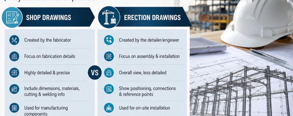
Core differences between the two
| Aspect | Shop Drawings | Erection Drawings |
| Purpose | Guide fabrication of individual pieces | Guide field assembly and placement |
| Used by | Fabrication shop | Field crew, ironworkers, crane operators |
| Detail level | Bolt holes, welds, dimensions per piece | Grid locations, sequencing, connections |
| Scope | One member at a time | Whole structure or building section |
| Timing | Created before fabrication begins | Referenced during construction |
| Common errors if wrong | Misfit parts, wrong hole spacing | Sequencing conflicts, field rework |
That table makes the split look tidy. On a live jobsite it’s not. A shop drawing mistake means a piece doesn’t match what was actually designed. An erection drawing mistake can mean a crew installs things in the wrong order, and a partially built structure that’s out of sequence is a stability problem, not just a paperwork one.
Why do both documents matter on a steel project?
Rush either drawing type, or skip it, and the cost usually shows up later, when it’s harder to fix. A 2023 survey from the National Institute of Building Sciences put U.S. construction rework tied to design and documentation errors at roughly $31 billion a year. Steel work, with tolerances that tight, ends up more exposed to that than most trades.
Moreover, shop drawings without erection coordination leave you with a shop full of correctly made pieces and no clear plan for putting them up. Erection drawings without accurate shop-level detail leave a field crew trying to fit pieces that were never dimensioned right in the first place. Neither one on its own gets you a finished, safe structure.
That’s the case for steel detailing services in USA that produce both drawing sets as one coordinated process. Conflicts get caught before steel is cut, not after a crane shows up on site.
Common mistakes contractors make
- Treating erection drawings as an afterthought- Some teams pour their time and budget into shop drawings and assume the erection sequence will work itself out on site. On anything multi-story or geometrically complicated, it usually doesn’t.
- Working off outdated piece marks- Shop drawings get revised late in a project more often than people expect, and the erection drawings don’t always get updated to match. Field crews end up referencing piece marks that no longer line up with what actually got fabricated.
- Assuming one detailer can handle both equally well- Fabrication-level detailing and field-level sequencing are different skill sets. A detailer who’s excellent at shop details isn’t automatically good at sequencing a 12-story frame, and it’s worth checking which one a provider is actually strong at.
- Skipping the connection design review- Erection drawings that don’t get checked against real field conditions, existing structures, site access, and how far a crane can actually reach cause delays that have nothing to do with the steel itself.
How do professional detailing teams handle this?
Experienced detailers build shop and erection drawings from a single coordinated model rather than treating them as separate jobs. They model the structure once, then pull both drawing sets from that same model, which keeps piece marks, dimensions, and connections consistent across both documents without extra manual checking.
That approach also catches clashes early. If a connection looks fine on paper but physically runs into an adjacent member, a coordinated model tends to flag that during detailing, when it’s cheap to fix, rather than during erection, when it isn’t.
12 Meter Engineering follows this approach on structural steel projects, producing shop and erection drawings services in USA from one detailing model so fabrication and field teams are always working off the same information.
Expert insights from the field
The detailing packages that hold up best on site usually aren’t the ones built with the most advanced tools. They’re the ones where someone actually walked through the erection sequence before the shop drawings were finalized. Asking whether a piece can physically be lifted into place in that order, at the shop drawing stage, catches problems that are close to impossible to fix once fabrication is done.
Bolt access gets overlooked more than it should. An erection drawing can show a bolted connection that looks fine on paper, but if an ironworker can’t actually get a wrench in there once the adjacent steel is up, that connection is a field problem waiting to happen. It’s a small thing to check. Experienced detailers check it. Not everyone does.
Wrapping it up
Shop drawings and erection drawings cover different parts of the same job, built for different people at different points in a project. Coordinate them from the start and fabrication stays accurate while field installation stays predictable. Treat them as two separate afterthoughts, and you’re more likely to find out about a mismatch on site, with a crane already parked and waiting.
If you’re planning a structural steel project and want your shop and erection documentation handled together instead of as two disconnected tasks, 12 Meter Engineering can talk you through how their detailing process keeps both in sync from day one.
Frequently asked questions
Shop drawings guide how individual steel pieces get fabricated. Erection drawings guide where those pieces go and how they’re assembled on site.
Fabrication shops use shop drawings to cut, drill, and weld steel members to exact specifications before they leave the shop.
Field crews, ironworkers, and crane operators use erection drawings to place and connect steel pieces in the correct sequence on site.
No. Shop drawings lack sequencing and grid information, and erection drawings lack fabrication-level dimensions. A complete steel package needs both.
A steel structure needs to stay stable while it’s being built, not just once it’s finished. Sequencing notes keep a partially erected frame safe to work on.
Mismatched piece marks or dimensions lead to field rework, schedule delays, and occasionally safety issues if crews install pieces in the wrong spot or order.
Not equally well. Some are stronger on fabrication detail, others on field-level sequencing logic. Look for a provider who handles both.
Alongside the shop drawings, not after. Planning erection early catches sequencing conflicts before fabrication dimensions are locked in.
In the U.S., weld symbols and specifications typically follow the AWS D1.1 structural welding code.
Documentation and coordination errors are a major driver of construction rework, which the National Institute of Building Sciences estimates costs the U.S. industry billions of dollars a year.