Table of Contents
- Key takeaways
- What does BIM mean for steel detailing?
- How does the detailing workflow change with BIM?
- Can clash detection prevent field conflicts?
- How does BIM support fabrication drawings and material planning?
- How does BIM help with erection planning?
- Practical scenarios from the Field
- What are the limits of BIM adoption?
- How does BIM improve accuracy and project delivery?
- Wrapping up
- Frequently asked questions
Building Information Modelling (BIM) provides steel detailers, fabricators, erectors, and general contractors with a single 3D model of the building. Rather than passing around different sets of drawings that may become out of sync, the model contains every beam, column, plate, and bolt group.
For steel construction, this means fewer conflicts in the field, neater shop drawings, and more consistent fabrication and erection delivery. Companies looking for Structural steel detailing services in the USA frequently require this type of coordinated, model-based approach as well.
Key takeaways
- BIM makes steel detailing a model-centric process, so one change updates all associated views.
- Steel detailing services in the USA become stronger when clash checks are done before material is cut.
- Model data creates fabrication drawings, cut lists, and erection sequences all from the same data source.
- Results depend on early agreement about standards, model levels, and responsibilities.
What does BIM mean for steel detailing?
BIM isn’t just a 3D image of the construction. The information is associated with every component in the model: the profile, the grade, the length, the orientation, the connection type, and so on. As long as the data doesn’t change, the model can generate reports, schedules, elevations, and plans without being hand-drawn. This is one reason BIM services in USA are now a common part of steel project planning.
However, the amount of detail counts. In a conceptual model, there may be only member centerlines, but in the fabrication-ready model you may see the coped ends, clip angles, base plates, and bolt holes. Frameworks like ISO 19650 for information management and the National BIM Standard-United States (NBIMS-US) can guide teams in understanding what information is required at what point in the project.
How does the detailing workflow change with BIM?
In a typical sequence, the engineer produces design drawings, the detailer deciphers them, and then the fabricator constructs them from shop drawings. At each of these transfers, there is room for error. With Building Information Modelling (BIM), the engineer’s intent flows into a sophisticated model, where the connections are designed and tested to the original design. Good Structural steel detailing services in USA follow this sequence closely, because each step builds on the one before.
A typical BIM detailing workflow is as follows:
- Design models or structural drawings are provided with load and connection requirements in the form of a design engineer of record.
- The detailer will put together a detailed model including connections, bolts, welds, and erection details.
- Internal checks of member sizes, clearance, and bolt access.
- The approved model is then used to generate Shop drawings and Fabrication data.
- Modifications are applied to the model so they all change with each output.
AISC 303, the Code of Standard Practice for Steel Buildings and Bridges, specifies the responsibilities for shop and erection drawings. BIM does not alter those responsibilities. It does, however, facilitate a quicker, more traceable review process.
Can clash detection prevent field conflicts?
Clash detection is a crucial benefit of BIM. The model is then checked against other trades, such as MEP (mechanical, electrical, plumbing), and concrete, and the software will identify any interference or conflicts.
Consider a common situation. An HVAC duct runs through a beam line that was sized before the MEP team completed its design. Clash detection reveals the problem during coordination, and the MEP group can choose to reroute the duct, engineer a reinforced opening in the beam, or alter the framing. Same problem on site, and you’re looking at a cut-and-weld fix, a postponed sequence, and an angry schedule.
Therefore, clash detection only works if it is run repeatedly, not just once ahead of time. Keep a dedicated list of outstanding clashes, owners, and due dates for every coordination meeting.
How does BIM support fabrication drawings and material planning?
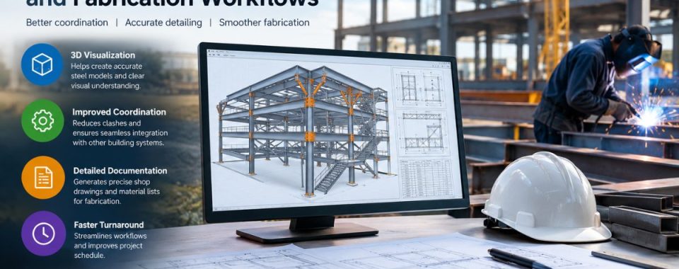
Shop drawing materials convert the model into guides for the shop. Piece marks, cut lengths, drilled hole patterns, weld symbols, and surface prep instructions are all extracted from the same model data. This minimizes transposition mistakes and ensures the shop is referencing the latest revision. A majority of fabricators now ask for steel fabrication drawings services in USA made directly from the coordinated model instead of redrawing from the design sheets.
BIM also helps with material planning. As the model is aware of the length and profile for each member, the quantities are automatically extracted for ordering. Nesting plans are planned to minimize offcuts, thereby limiting wastage and cost. Counts of bolts and welds are more straightforward, and the fabricator can schedule shop capacity accordingly.
| Stage | Traditional approach | BIM-supported approach |
| Design revisions | Manual markup of drawings | Model updated once, views refreshed |
| Clash checks | Overlays on paper or PDF | Automated clash reports |
| Material takeoff | Manual counts and spreadsheets | Quantities extracted from model |
| Fabrication drawings | Redrawn from design sheets | Generated from approved model |
| Erection planning | Separate sequence documents | Linked to model and schedule |
Weld and connection specifications must comply with the applicable regulations, that include AWS D1.1, the Structural Welding Code for Steel, and AISC 360 for its design. The model reflects the requirements of the code and does not substitute for engineering judgment.
How does BIM help with erection planning?
That’s where little mistakes cost you dearly: erection. BIM enables the erection team to visualize the structure in sequence, access for bolting and welding, and to determine the location of temporary bracing required before a member is lifted.
Furthermore, sometimes models can be integrated into a schedule to indicate the building being constructed over a period of weeks, known as 4D modelling. It is helpful for positioning cranes, laydown areas, and lift weights. The erector can also check on the position and orientation of each piece prior to it being delivered to the job site to minimize time spent searching for the “right” member.
Some teams use the model to create erection drawings, bolt-up sequences, and anchor rod layouts. Field checks are still important, but this shared reference is provided by the model.
Practical scenarios from the Field
The following are examples of some of the typical patterns found in steel works projects, and are not descriptions of specific projects.
- Scenario one: anchor rod misalignment. A concrete contractor installs anchor rods according to a 2D plan. The model is overlaid on the foundation survey; the result is that the team finds that two rods are offset from the base plate holes. This problem is detected prior to the arrival of steel, and thus field drilling or re-setting of rods is avoided.
- Scenario 2: Changing the size of the beam. The engineer decides to redesign and increase the size of a girder late in the design phase. When the change is done in a model-based workflow, it will trickle down to the connection details, material list, and shop drawings. The detailer may not be able to find the time to make several hand corrections to various sheets without BIM, and a missing sheet might end up in the shop.
- Scenario three: crane access. A model is sent to an erection planner who determines that a column line is within the swing radius of a planned crane position. The sequence is tweaked before mobilization to avoid a rigging change on site.
What are the limits of BIM adoption?
BIM is not an easy switch. Expectations need to be realistic for teams.
- Investment: Software licences, hardware, and training costs need to be invested in, particularly in smaller shops.
- Interoperability: Different kinds of platforms can create models that don’t share data easily, so file formats and methods for transferring data must be agreed.
- Mismatched expectations: These might range from one party wanting the level of detail to be fabricated, to another party wanting a conceptual model, creating scope issues.
- Ownership and liability: Agreements should clarify who owns the model, who is responsible for maintaining it, and who bears the responsibility.
- Excessive modelling: Modelling too much detail is not adding value to the project and may delay work.
- Dependence on quality: A model is only as reliable as the data entered. Bad input leads to good-looking but incorrect output.
When comparing steel detailing services in USA, teams should seek the answers to these questions in writing from each of the Steel detailing services. Having a clear BIM execution plan for standards, model levels, coordination schedules, and quality checks takes most of the guesswork out of the mix.
How does BIM improve accuracy and project delivery?
Accurate information is better when the model is the one source, as fewer people are working on outdated information. Consistent revisions minimize requests for information (RFIs), which can slow projects down, and clash detection minimizes rework. Fewer surprises in erection are also welcome benefits of better planning.
Collaboration also lends itself to improvement. Engineers, detailers, fabricators, and erectors can share the same model and discuss problems, instead of lengthy email threads. This will lead to more successful project delivery and communication with the owner and general contractor over the long haul.
Wrapping up
BIM provides steel projects with a shared, coordinated view from design to erection. In addition to the above, it aids in the early detection of clashes, more accurate fabrication drawings, better material planning, and more predictable erection. It also poses real challenges, such as training and interoperability, and having clear responsibilities and management, which must be taken up purposefully.
The real issue for engineers, detailers, fabricators and contractors is not whether to use BIM, but how to use it effectively. The benefits are generally obvious when teams establish standards at the outset and maintain their models up to date and review the clashes on a regular basis. When detailing is required for your project, the ideal location to begin is with a provider that has proven coordinated and has a method. This is where the best Structural steel detailing services in the USA start.
Frequently asked questions
BIM for steel detailing is a modelling-based process where members, connections, and related data are created in 3D. Consistency of shop drawings, reports, and material lists is maintained with the model, thereby ensuring consistent information in the design, fabrication, and erection.
Not always. The scope differs according to the provider and contract. There are some that only provide modelling and clash detection capabilities; others provide full shop and fabrication drawings. Verify and confirm deliverables and model levels before work.
Yes. If changes are made to the approved model, revisions will automatically be updated when drawings are generated. This helps to minimize transcription errors and helps maintain a running list of information.
It finds overlaps in steel trades with other trades, like ducts, pipes, and concrete, prior to fabrication. The cost of resolving conflict in the model is much less than cutting or re-welding members on site.
Examples include AISC (303 detailing responsibilities, 360 design, 364 welding, 366 information management and ISO 19650) and NBIMS-US (welding, BIM practice). There may be additional requirements as defined in the local projects.
It can help. Correct quantities and nesting minimise over-ordering and offcuts. The actual savings will vary with the size of the project, shop practices and adherence to the material plan.