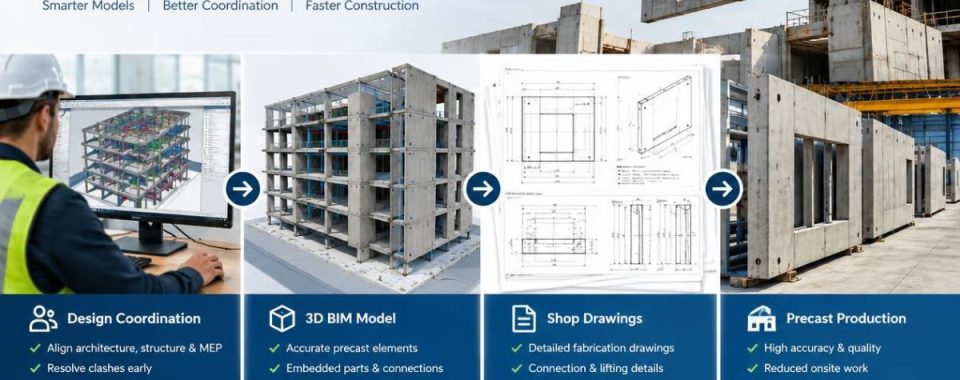
BIM implementation in precast concrete refers to the process of using a common 3D model to coordinate all panels, connections, lifting points, and embedded elements before the actual fabrication process begins. Clashes can be solved at the desk instead of on the construction site, and shop drawings are made from approved models. As a result, there would be fewer changes being made to the design, faster approvals, and better installation.
This blog explains how this workflow progresses from the initial design coordination to the generation of shop drawings ready for production, as well as what aspects the project teams in Australia should pay attention to when choosing the company to work with.
Key takeaways
- BIM provides precast teams with a single 3D model that will identify clashes prior to casting.
- The benefits of early contact by the detailer will benefit cost, programme and buildability.
- Shop drawings produced from the model are accurate to design intent and facilitate easy revisions.
- In Australia, a good partner will help minimise risk by having effective coordination processes in place and local experience.
What is BIM for precast concrete and why does it matter?
Precast concrete is produced in a factory with controlled conditions and delivered to the site for lifting into place. Each panel, beam, or column is cast before it gets to the building, so all the dimensions, openings, and connections must be right long before the first crane lift. This is why the design information for precast production is very important.
BIM, or Building Information Modelling, provides the project team with a single digital environment where all building information is stored together – including architectural, structural, mechanical and electrical information. For precast, this is a benefit for checking the panel layout, reinforcement, lifting inserts, bearing details and service penetrations in 3 dimensions. There is no longer any need to compare individual drawing sheets and hope the numbers match.
It is becoming common practice for many contractors in Australia to hire precast detailing services that directly work from a BIM model and not from the conventional 2D drawings. This change affects the way that responsibility is distributed, the re-use of information, and the rate at which a project can progress from concept to casting. It also provides a better understanding of what is being created for all stakeholders.
Moreover, the advantages are not only in the drawing room. A coordinated model facilitates improved quantity take-offs, accurate procurement, and reliable programming. If the factory can trust the information, it will be able to make fewer stops and starts in its production. This makes the model a useful tool for the whole project, instead of a document in a folder.
Why does design coordination matter so early?
Design coordination is the phase of the project when the various systems are coordinated. Late changes in a precast project have a greater impact, as they can impact casting moulds, loads, and crane schedules. One hour to resolve a clash on the screen can be weeks after a panel has been cast.
So it starts at schematic design and continues when the fabricator is engaged, and not after that. So it starts at schematic design and continues on once the fabricator has been engaged and not after. As long as the width of the joints, panel sizes, and connection methods are easily adjusted, the detailer can run tests at this early stage. It also enables the design team to identify those decisions that will have the most impact on cost and programme.
It is easier to build the design if it is coordinated early. The weight of panels can be verified with the crane capacity; transport restrictions can influence the choice of the length of the panel; repetitive units can be standardized for re-using moulds in a cost-effective way. All of these selections are easy to change in a model, but difficult to change on-site. As time passes, the number of variations is cut down, and the project remains within the budget.
Therefore, coordination activity is also a communication activity. Each of the architects, engineers, builders, and fabricators approaches the project with a unique perspective. Everyone has a common reference point, and decisions are recorded and traceable in a shared model and through regular review meetings. This clarity is significant if there are multiple design revisions underway.
Common clashes found during coordination
There are a few common areas of coordination where most clashes tend to occur. Early recognition enables project teams to establish checks to detect issues before they make it to the factory floor.
- Anchors and cast-in plates that interfere with reinforcement, where lifting anchors or cast-in plates interfere with the bars in the panel.
- Service penetrations that don’t match the structural openings, possibly cutting or patching after erection.
- Overlapping bearing seats, dowels, and grout pockets that do not fit together
- Poorly formed panel joints in awkward positions – weatherproofing, acoustic and visual –
How does the coordination workflow run: step by step?
There’s a clear process in well-run coordination. The output of each step is defined, and the output of each step is the input for the next one. This will keep the project on track and will ensure that teams are not using outdated information.
- Find common coordinates, levels, and grid lines and use them as a common starting point for all disciplines.
- Draw the architectural and structural base model including floor levels, openings, and important load paths.
- Create the precast panel model, adding reinforcement, embedded items, lifting points, and connection hardware.
- Conduct clash detection in all disciplines and classify each clash according to the severity level.
- Solve problems at a coordination meeting and put all decisions into an issue log.
- The coordinated model is to be frozen at the agreed revision to start shop drawing production.
In reality, this flow is not a linear process. Many times, revision steps go back to previous steps because the changes in design impact layout or connections of panels. This is why version control and communication are as crucial as the modelling itself. The table below provides a summary of the typical leader and the content of each stage.
| Stage | Main Output | Typical Lead |
| Concept layout | Panel zoning plan | Architect and engineer |
| Structural coordination | Connection strategy | Structural engineer |
| Detailed modelling | Coordinated 3D panel model | Precast detailer |
| Clash review | Issue log and resolutions | Design team |
| Model release | Approved model for drawings | Engineer of record |
How are shop drawings produced from the model?
- The working drawings the factory uses to cast, reinforce, finish and load each element are referred to as shop drawings. They are created from the coordinated model in a BIM workflow, instead of being redrawn. Therefore, dimensions, quantities and bar schedules remain unchanged from design, and when changes are made in the model, they appear on the drawings as well.
- Precast Panel Shop Drawings Australia is best when the model is considered the one true data source. All sheets, schedules, and details are tied to the same underlying data, ensuring that there is no chance for different information to be found in different drawings and in the physical element. This linkage also makes revision control easier – one model change is reflected throughout the entire drawing set.
- Automation further speeds up production. Repetitive panel types can be created from the standard templates, and the bar bending schedule can be directly retrieved from the reinforcement layout. This means that the drafting team can focus more on intricate details and less on mundane work. However, although the output is automated, it must also be reviewed, as a template applied to an atypical panel can result in errors being carried over in the drawings.
- Prior to release, the drawings must be verified with the model; the engineer of record checks them for design intent. This second check discovers conflicts between the model and the drawing set, which is particularly useful on large projects having hundreds of different panels.
What should a shop drawing package include?
A full package enables the factory to cast and send out each element without a question. These are all to be expected in each panel type.
- Elevation and plan views, overall panel dimensions and locations of openings
- Clearly marked reinforcement layout with bar marks, sizes and spacings
- Information about lifting, propping and erecting, such as lifting points and sequences required.
- Embedded item schedules, connection details and tolerances
- Finish and surface requirements, such as face and texture of formwork
- Bill of materials and bar schedules for fabricating and ordering
Which BIM and detailing services should Australian projects consider?
Australian projects are run with strict requirements for structural performance, fire safety and construction tolerances, and this means a partner is crucial. When considering BIM services in Australia, project teams should question their providers to understand their local design practice, referenced standards, and how precast is delivered in various project types from state to state. A provider who has been involved with projects similar to this one will expect to know what issues may arise that a generalist has not.
A good precast detailing services in Australia supplier must merge the abilities of modelling with practical engineering judgment. They should be able to describe how they work with architects and structural engineers, how they deal with model changes and how they pass information on to the factory. Good providers will also highlight design decisions which could impact transport, lifting or installation, before they become pressing concerns.
Drawing support does not end with the issuance of drawings. There are a lot of questions that come up when making the product and when setting it up, such as tolerances, substitutions, and site changes. Having a detailer on hand who can get the model updated quickly can help the project get back on track without losing steam. This is why communication is crucial, as well as revision discipline, alongside technical ability.
How do you choose the right detailing partner?
The choice of the detailing partner can have an impact on cost, programme and quality throughout the life of the project. The comparison below highlights the criteria that are most important when evaluating candidates. Serve as a checklist for tender interviews and references.
| Criteria | What Good Looks Like | Why It Matters |
| Coordination process | Scheduled model reviews and a maintained issue log | Keeps design changes traceable |
| Model quality | Accurate embeds, reinforcement and openings | Reduces errors at fabrication |
| Drawing output | Drawings generated directly from the model | Keeps sheets consistent |
| Local experience | Familiarity with Australian standards and delivery | Avoids costly rework |
| Communication | Clear revision control and defined response times | Protects the programme |
When evaluating a precast panel detailing services in Australia, request to see their sample of coordination reports and a sample shop drawing package. Check the documentation of decisions made by the provider and ownership and closure of issues in their issue logs. These artefacts show much more about the working practice than a company brochure.
Talking with former clients is another benefit. Ask
- Do you receive drawings in time?
- How many revisions did it take to get it right, and was there adequate information for the factory?
- When you get honest answers to these questions, you will have a realistic idea about what you can expect on your own project.
Bottom line
BIM for precast concrete moves the problem-solving process from the construction site to the design office, where it will be easier and more economical to make changes. A disciplined workflow ensures all stakeholders are on the same page – and all panels fit for purpose – from the first coordination meeting through the final shop drawing. Delivering something complex can be predicted when it is carefully planned at each stage.
Enlist the assistance of an experienced team that provides precast detailing services in Australia, and you will have a smooth installation, or you will find yourself sitting on your hands for months. Selecting the right BIM services in Australia partner is the way to safeguard your programme and budget, whether its full model coordination or final drawings. At 12 Meter Engineering, they are able to coordinate the models and use their practical experience in fabrication to help projects run smoothly from design to site with fewer surprises.
Frequently asked questions
BIM for precast concrete extends from 3D modelling to clash detection, connection design coordination, through to shop drawing production for fabrication.
Coordination should begin early in the schematic design phase, after the definition of the grid and panel zones; issues should be raised before the beginning of fabrication.
The engineer of record reviews shop drawings, with builder input, and approves them before any panel is cast.
Yes. Clash-free models and accurate embed locations minimise on-site cutting, remedial work, and crane delays, resulting in lower overall cost.