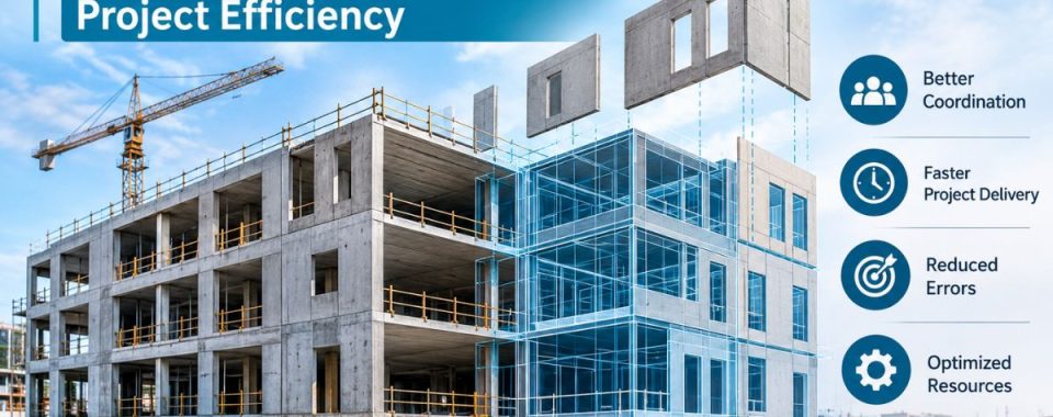
3D precast modeling increases the efficiency of construction projects and improves coordination since every panel, opening, embed, and rebar is shown in one exact digital model. The collaboration of architects, structural engineers, precast producers, and site crews makes finding clashes possible on the model surface rather than at the job site. As a result, there are fewer revisions, quicker approvals of the project, less material waste, and easier installation.
This method makes precast construction in Australia predictable. The next sections will explain how it works, what savings a client may achieve, and how to choose the appropriate detailing partner.
Key takeaways
- 3D precast modeling is done by placing all elements, connections, and reinforcements within a single shared digital model prior to manufacturing.
- Clash early detection helps avoid expensive redesigns of sites and schedules.
- Precast Panel Detailing Australia works well due to accurate panel details and checked drawings for fast production rates.
- Selecting an organization that has good communication systems, open access to change management tools, and a solid track record of success will lead to better outcomes.
What is 3D precast modeling and why does it matter?
3D precast modeling involves the creation of a comprehensive digital model of precast concrete components, such as geometry, connections, embedded objects, and reinforcement. It is finished before the fabrication process starts, for design purposes, to be verified against the manufacturing and installation reality. The model becomes the only source of truth for all disciplines of the project.
However, precast elements include wall panels, hollow core slabs, columns, beams, staircases, façade units, etc., which are manufactured in a controlled factory environment. While that is a good thing, it is also a costly mistake. If a misplaced sleeve or a missing lifting insert is found after casting, it might be necessary to demolish, remanufacture, or book a delayed crane. A coordinated model can help mitigate those risks by enabling teams to spot issues before they become costly to fix.
A lot of companies, which provide precast detailing services in Australia, now take modeling as a part of their job. The client should inquire about the process of building the model, who reviews it, and how changes are transferred from the design team to the factory. The answers provide insight into whether the provider views modeling as a legitimate engineering tool or as a presentation feature.
- How 3D Precast Modeling Works
Most workflows start with the architectural and structural design. Detailers then use that information to create a model of the object that displays everything at the correct size and location. Bolts, plates, and weld zones are modeled to represent connections. The reinforcement is positioned according to design code and casting plan. Lastly, shop drawings, bills of materials, and production schedules are created using the model.
It is a process that is repeated. If the design changes, the model is updated, and drawings that are affected by the change are reissued. A good detailing company has a record of revisions to make sure that they are all aware of the current version. If that discipline is not followed, a factory can wind up creating a casting from a drawing that is 100 years old, and it won’t become apparent until the element gets to the site.
- Where It Fits in the Project Timeline
The most useful use of 3D modeling is in the early stages of detailing when there is still flexibility in design choices. The design team will be better informed about the way panels will be lifted, transported, and installed with the modelling of the early stages. It also enables the construction team to schedule the delivery sequence to avoid having too many deliveries on the same day. The modeling process is concurrent with a project’s procurement process in many projects, reducing the schedule of the project.
It is still useful to model at the end of the process, but it becomes increasingly expensive. After moulds are constructed and reinforcement is installed, even slight changes may result in redesigning components. That’s the reason all project managers who have any experience in the field encourage the modeling process, regardless of whether it is as a final check or not.
How does 3D modeling improve coordination between trades?
One of the major causes of delay on most construction projects is coordination. Precast elements join structural steel, mechanical services, electrical conduits, plumbing risers, and architectural finishes. Each trade uses its own drawings, and only show mismatches when crews attempt to build on-site.
This is when 3D modeling comes into play, as it brings all the disciplines together in one place. The reveal lines of a panel can be seen by the architect in relation to windows and balconies. Engineers can verify that the connection is sufficiently wide for bolts and access for welding. Services engineers can install pipes in sleeves, which are installed where they are required. The same geometry is used in each discipline, making decisions quicker and reducing arguments over who drew it to be correct.
The complexity of Mixed-material buildings is added. Precast walls are normally joined at the corners to steel frames, and the joints need to line up exactly. Collaborating with precast and structural steel teams to bridge the gap at these points helps avoid this. Likewise, BIM services in Construction Coordination enable all disciplines to stay informed with the same up-to-date information.
- Early Clash Detection
Clash detection determines if two elements are in the same space. This is much cheaper than doing it on site rather than in the model. Typical conflicts include a duct through a beam, a sleeve too near to a reinforcement cage, or a buried plate that prevents an anchor bolt. A few stoppages can be avoided by a short discussion at the site for all clashes identified in the model.
Teams typically perform clash checks at specific milestones, like after the architectural model is issued, the structural model is developed, and before shop drawings are issued. Frequent inspections can help you avoid big redesigns. They also help to create confidence across stakeholders since the problems are identified and addressed in a transparent and documented manner.
- Shared Information for Every Team
If no one can get access to information, then a model is not useful. Good coordination involves everyone involved in the precast assembly project, the precast manufacturer, the erector, the concrete supplier, and the project manager- being on the same version of the project. If all parties are using a single source, meetings are shorter, and decisions are well documented. This can help answer questions that previously required days of email exchange by looking at the model together on screen.
Furthermore, shared information also helps to hold people accountable. If a revision is made, the model will keep track of who made the revision and when. That history helps defend the project when later on issues come up as to why they did it this way.
How does 3D precast modeling increase project efficiency?
Efficient precast construction is defined as creating the correct element at the correct time, with the correct information and no rework. All four goals can be achieved with 3D modeling. It cuts down the amount of time between design and production, minimises change, and enhances the accuracy of quantities ordered and scheduled. The following table shows the differences between the traditional way and the modeled workflows.
| Area | Traditional 2D Drawings | 3D Precast Modeling |
| Clash detection | Mostly manual, often found on site | Systematic and completed in the model before casting |
| Quantity accuracy | Estimated from separate drawings | Calculated directly from the model |
| Revisions | Frequent and often discovered late | Fewer, and caught earlier in the process |
| Site installation | More surprises and on-site adjustments | Smoother, with clear lifting and fixing details |
| Team communication | Relies on separate files and long email chains | One shared model with a single current version |
- Fewer Site Revisions
Site revisions are expensive due to impacts to labour, equipment and schedule. Once a precast element is cast, it is difficult and costly to change it; this frequently involves redesigning the precast or compromising with a lower quality design. A coordinated model minimizes these changes by resolving conflicts before production. A small decrease in revisions over the duration of a project can save precious time and money.
- Faster Production and Fewer Material Errors
Accurate models create accurate shop drawings and bar schedules. If the bar bending schedule is drawn out from the same model as the mould drawings, then the chances of errors in the transcription are reduced. Casting teams can start earlier because they have more confidence in the information they are presented with. Ordering of materials becomes more precise, thus minimizing steel and concrete shortages and overages.
Additionally, accurate ordering also helps to maintain a more balanced cash flow as materials are ordered at the appropriate times and not in large quantities on a speculative basis. Production planning is also helped. The model can be designed to reflect exactly which and how many elements are required for each floor or zone, allowing the factory to synchronise casting with erection. This prevents large quantities from being stored on site and helps to maintain a tidy yard.
How can precast panel detailing become more accurate?
Precast Panel Detailing Australia can benefit from modelling, as panels can often be the most visible and repetitive elements on a building. If the same mistake is made on fifty panels, it’s a big problem. Accurate detailing guarantees accurate panel consistency, accurate fixing points, and accurate lifting insert placement within the correct tolerances.
Another factor in the design of a panel detailing is also to take into account the building envelope. Joints need to allow for movement; facades need to fit seamlessly into the drainage details; and the depth of all the insulation layers must fit into the panel depth. A model captures these relationships and can be used to test the design prior to construction of the formwork.
- Panel Layout and Reinforcement
The first element in the panel layout is dimensions, openings, and reveals. The model illustrates the reinforcement to be used in the panel thickness and around openings. Detailers verify the spacing of covers, bars, and placement of starter bars, which are connected to other components. The reinforcement displayed in 3D can be verified more easily than a set of two-dimensional sections, particularly for complex geometry like curved or angled panels.
Reinforcement quality is closely linked to the level of detail of the reinforcement. Read our article on precast reinforcement best practices to get practical advice. For those looking for rebar detailing support, you can also check our rebar detailing service for Australian projects.
- Connection and Lifting Details
Precast elements most frequently do not fit well where connections are. By modelling every connection with its plates, bolts and welding zones, the team can establish clearances before casting. The same care is required for lifting inserts. The model can demonstrate their position in relation to the centre of gravity to assist the erector in planning a safe lift and prevent unexpected tilting while handling the erector.
The connection information is also used in sequencing on site. In cases where a panel has to be fixed before an adjacent element can be placed, the model shows this as early as possible. This understanding enables the erection plan to be set up in such a way that no crews are waiting for one another.
What should a fabrication drawing set include?
Precast fabrication drawings services in Australia provide a robust set of drawings that convey the design to the factory without any guesswork. Drawings are to be complete and in agreement with each other and clearly versioned. If a gap in a drawing set occurs, the factory will have to halt and ask for clarification, and this will result in delays.
Fabrication drawings are also used as a quality reference. They can be used by inspectors to inspect the completed units and by erectors to verify fixing points. A well-laid-out drawing set will save time throughout the project.
| Drawing Type | What It Shows | Main Users |
| Elevation and section drawings | Overall geometry, dimensions, and openings | Casting team and engineers |
| Reinforcement layouts | Bar sizes, spacing, cover, and starter bars | Steel fixers and quality teams |
| Embedded item drawings | Inserts, plates, sleeves, and lifting points | Casting team and erectors |
| Mould drawings | Formwork dimensions and joint locations | Mould makers and casting team |
| Bar bending schedule | Bar lengths, shapes, and quantities | Reinforcement fabricators |
Key elements of precast fabrication drawings
The following are key components of every fabrication set:
- Specify dimensions and tolerances for each component.
- Reinforcement schedules consistent with the applicable design codes
- The accurate position of the embedded items, sleeves, and lifting inserts
- Handling, storage, and transport information for the site team.
- A revision history and Approval Status for each sheet.
For more details on how drawings are created from the model, check out BIM for precast concrete: design coordination to shop drawings. It gives a description of the conversion of design information to instructions used in the factory.
Quality Checks Before Release
Drawings must be reviewed in a structured manner before leaving the office. These include checking the dimensions with the most recent architectural model, checking that there is no reinforcement obstruction to embedded items, checking lifting points against the weight and centre of gravity of the element, and ensuring quantities are consistent with the bill of materials. A detailer that is independent of the person who did the initial detailing can be helpful, as the first person may have missed mistakes in their work.
How do you choose a reliable detailing partner?
Choosing a precast detailing company in Australia becomes simpler once you know what to inquire about. Knowledge of the particular types of elements is helpful, but the way a company handles communication and revisions is as well. Request to view examples of drawings, photos of screens, and a precise explanation of the coordination process. A trusted partner will be able to walk you through its checking process.
Projects involving multiple materials may require a partner with expertise in multiple disciplines. Structural steel detailing for Australian projects is available that can coordinate both structural steel and precast systems within a single process if your building uses structural steel. This minimises the number of handovers and the chances of misinformation.
Questions to ask before hiring
When searching for a deal, feel free to ask the following questions before signing an agreement:
- Are there more recent projects with similar element types that you know of?
- What do you do when a drawing is issued and then changes are made to the design?
- What type of clash detection and checking processes do you employ?
- What is your approach to communicating changes to the site team and the factory?
- When time is of the essence, how fast can your team react?
Moreover, the responses should be specific. Vague replies about “advanced technology” or “experienced staff” are less useful than a clear description of a process you can verify.
Bottom line
3D precast modeling is not an expert specialty anymore. Practical for improving teamwork efficiency by reducing duplication of work while keeping things going smoothly. Resolving conflicts between models helps to avoid delays for both factories as well as sites by providing them with accurate timelines and budget estimates. The benefits of this approach are greatest if you start modelling early on by checking your drawings against an independent standard beforehand so that everyone is working off a common model at all times.
For precasting projects, if you need help understanding model timelines for them, please reach out to us so we can assist further.
Frequently asked questions
3D precast modeling helps coordinate precast components, identify conflicts, and create precise drawings before casting starts.
Early detection of conflicts leads to fewer changes at sites for revision or remodeling while increasing precision in terms of quantity, thus reducing labor, materials, and schedule expenses.
A precast construction drawing set provides a good-quality product, such as elevation plans, reinforcement layout diagrams, position of embedded items on site sheets, and instructions for the installation process.
No. Small-scale projects are less prone to error at a single location, whereas big ones get the benefits of better cooperation among various departments.