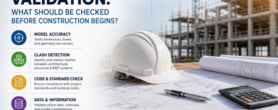
The purpose of BIM model validation is to ensure the building information model is accurate, coordinated, and complete before any construction work starts. Validating a model ensures that it is free from clashes, is set up using agreed-upon coordinates and naming conventions, and contains all relevant information so that it can be used for procurement or fabrication.
Validation of a structure involves verification of connections, member specifications, and the readiness of the structure for construction. As a result of not validating the model, various complications such as the need for rework or delays in the process may arise. This guide describes verification steps for each stage of the model validation process.
Key takeaways
- Check for geometrical accuracy of dimensions and coordinate positions prior to making purchase orders or manufacturing plans.
- Ensure models are accurate to quantity requirements, specification details, as well as installation sequence rather than just appearance quality.
- Steel connection bolts to bolting accessories for assembly sequence is given equal importance as an overall coordinate of it.
- Every check, approval, and accepted item should be recorded for an accurate record of what was done on this project to have evidence that it is complete.
What is BIM model validation and why does it matter?
BIM model validation is used to review a building information model in a structured way, prior to the beginning of construction work, against the project’s requirements. It verifies the model’s geometric correctness, interdisciplinary coordination, and abundance of data for construction. Validation verifies that the model reflects the design and that it is a dependable foundation for purchasing and installation.
The model is used to order materials, to plan the sequence of construction, and to prefabricate construction elements. If there are any deviations (errors) in the model, they are directly transferred into purchase orders, site instructions, and fabricated parts. When a conflict occurs on a screen, much less is spent fixing the conflict than if it had to be cut apart a finished wall or re-ordered a steel member.
Validation also safeguards the design team. Checks, approvals and issues, neatly documented, indicate that the model has been reviewed prior to release. That record is useful if questions arise regarding scope or design changes or responsibility. A number of organisations have built-in validation stages in their contracts, so that the process becomes an integral part of the project service, and not an add-on.
What core geometry and coordination checks come first?
The basic elements of any validation process are geometry and coordination checks. These checks ensure that each element is in its correct place, the correct scale, and positioned in the common project frame. If the initial geometry is met incorrectly, all subsequent checks become suspect. The following table outlines the key areas and the potential risks that can result from not addressing them.
| Check Area | What to Verify | Risk If Missed |
| Clash detection | Conflicts between structure, services, and architecture | On-site rework and schedule delays |
| Dimensional accuracy | Element sizes, spacing, and permitted tolerances | Components that do not fit |
| Coordinates and levels | Shared origin point, grid alignment, and floor levels | Misplaced elements across files |
| Model completeness | All required elements are modelled at the agreed level | Missing scope and unplanned variations |
| Version control | Every discipline uses the current revision | Work built to an outdated design |
- Clash detection between disciplines
The first type of check that teams typically perform on a coordinated model is a clash check. It detects where elements of different disciplines are present in the same location, like a duct going through a steel beam or a pipe crossing a steel column. There are some hard conflicts, where two objects meet in space. Others are soft clashes, involving an element intruding into a specified access space, insulation, or maintenance space.
A design change is not required for all collisions. A good validation process categorises conflicts by severity, assigns an owner to each one, and gives a clear deadline for them. When two disciplines collide again and again, there may be a bigger coordination issue, like missing early meetings or zoning issues. Solving the root cause will save time compared to solving each clash individually.
BIM coordination services can help a team if they require more capacity to conduct clash reviews on a regular basis and record the solutions for each clash. When reports are consistent, the design team is kept up to date and will not have to face the same problems on subsequent revisions.
- Dimensional Accuracy and Tolerances
The dimensional accuracy checks ensure that the parts are accurate in dimension and that gaps and offsets are within specified tolerances. Where prefabricated products have to conform to the condition to be installed – steel connections, curtain wall panels, precast units – tolerances become of the greatest importance. Model errors can increase in size if parts are manufactured with a slight deviation from the model.
Validators should validate not just the presence of objects, but critical dimensions to compare them to the design intent. They should also verify that the model has the same units throughout the files. An error that can be very costly is when the units of measurement are not the same, or when millimetres and metres are not the same.
- Coordinates, Levels, and Georeferencing
All the discipline models get the same origin, coordinate system, and level datum. If not aligned, files that appear correct on their own won’t align when merged. Before the start of any clash review, it is the validator’s responsibility to make sure that survey points, grid lines, and floor levels are consistent for all models.
Georeferencing is a special issue to address on projects that involve existing buildings or difficult sites. If an incorrect base point is used, then the whole structure gets moved by a few metres in the combined model, resulting in a lot of unnecessary clashes and effort. One of the easiest ways to safeguard the remaining validation process is to confirm these settings early.
How should model data and information be verified?
A model is more than geometry. All elements contain information for scheduling, cost planning, facilities management, and fabrication. This information should be validated to ensure it exists, is consistent, and is usable. Even if the model is perfect, if it doesn’t have all the data needed, serious issues can arise when the project gets into the procurement and construction phases.
- Naming and Classification Standards
By having consistent naming and classification, teams can filter, search, and report on the model with confidence. To ensure that element names, families, types, and system classifications match the agreed project standard, the validators should check. Labels are hard to interpret and extract quantities with; inconsistent naming makes it slow and error-prone, and it can also make automated checks that rely on the labels more brittle.
Moreover, it would be helpful to post a small naming guide at the beginning of the project and verify compliance in each review iteration. Teams that omit this step will find out at the end of the project that thousands of elements have different labels for the same piece. It’s much more costly to fix the rules in the aftermath than to do so initially.
Their BIM model data standards guide how to apply these standards across the structure of different-sized projects, including naming conventions and classification systems.
- Level of Development and Information Completeness
The amount of detail and reliability an element needs to be at each stage of a project. Validators should verify that the elements are at the appropriate level for the current milestone. Modelling the element too loosely for fabrication, and too precisely for early concept design are both indicators of information plan gaps.
Completeness checks are used to identify the missing required properties. Common examples are material grades, fire ratings, supplier references, and installation sequences. The validators can perform simple reports, which show elements with missing mandatory information; they can assign owners to fill the missing information before it is issued.
- Properties Needed for Procurement and Fabrication
Accurate quantities and specifications are essential for procurement teams. Each element must have the proper properties for ordering materials, such as size, grade, finish, and quantity, which must be validated. Inaccuracies or missing information here result in the wrong orders, late deliveries, and supplier disagreements.
More information is required, such as the lengths of the members, cut sizes, weld position, and bolt size for fabrication teams. These properties should be compared to design calculations and fabrication standards that will be used to direct work. Clear ownership of each property prevents confusion when questions arise during production.
Which structural steel checks matter before fabrication?
On a project, models of structural steel components can have some of the highest stakes associated with validation. Changes are expensive and time-consuming after steel cutting, drilling, and welding. When working with a structural steel detailing services in Australia, a team will go through a specific validation step prior to sending out any data or fabrication drawings.
Typically, a steel detailing fabrication service will include connection geometry, bolt access, member consistency, and erection planning. These areas can uncover some issues that are not discovered at a regular coordination review.
- Connection design and bolt clearance
The area where structural steel often doesn’t fit together is connections. It is important for the validators to ensure that there is sufficient space available for bolts, spanners, and welding equipment in every connection. They should also ensure that plates, angles, and stiffeners do not obstruct other components like ducting, cable trays, or the fire protection system.
Bolt clearance checks are particularly critical in tight areas like roof trusses, service cores, and moment connections. The connection may be visually good in the model but may not be able to be tightened using standard tools. With the installation team in mind, reviewing these areas can help avoid costly site modifications.
Therefore, steel detailing teams must also verify the type of connections with respect to the structural design assumptions. Even with perfect geometry, a pinned connection modeled as a rigid connection will give incorrect load paths. They should be checked by the structural engineers against their calculations before fabrication is started.
- Member sizes, grades, and section consistency
Member validation is used to ensure that each steel section is the same as that approved. The section size, steel grades, and member orientations should be verified with the structural schedule on the pieces in the field. If a single section is incorrectly set in a repeated bay, and the modelling is repeated, the error will be propagated throughout the frame.
Surface treatment and finishes are also considered consistent with the sections. Fabricators need to clearly identify the members that are to be coated, and ensure that the proper coating or primer is applied. It should be verified that finish requirements are not just taken into informal notes but are captured in the model.
- Erection sequence and site access
A perfectly-constructed steel frame can lead to delays if it cannot be safely and efficiently erected. The erection sequence should be reviewed to ensure the ability of members to be lifted into position, as well as the cranes to reach the required locations, and temporary bracing to be considered. The stages of erection should leave the structure stable.
Another important consideration is access to the site. Large members may have to go through areas smaller than they are, and some areas may need special attention. These constraints can be validated and modified before steel is ordered to ensure the team may perform optimally.
What documentation and approvals are needed?
If the results of validation are not recorded and approved, then it is not useful. A clear documentation record of the checked, changed, and accepted final model. It documents what was done by the project team to ensure that there is a record of the project team’s decisions in case there is any dispute and to ensure that new members have a historical record to work with.
- Model Information Exchange
Models, reports, and issue logs should be shared in an agreed way between teams. Every change should have a version number, a date, and a brief description of the change. Version control removes the usual headache of having to work on different versions without being aware of it in other disciplines.
Validation reports must be brief and to the point. A good report includes the following information for each issue: Location, severity, owner, and status. Reports that are long and unstructured are usually ignored, and reports that are focused lead to faster resolutions.
- Sign-Off Responsibilities
Each validation milestone should be assigned to an approver. The following table displays a typical approval path, but the role may differ between projects and contracts.
| Stage | Required Approval | Typical Owner |
| Concept model | Design intent confirmed | Design lead |
| Coordinated model | Clashes resolved and signed off | BIM coordinator |
| Fabrication model | Steel details checked and released | Detailing lead |
| Construction issue | Final model issued for site use | Project manager |
Sign-off should not take place until the significant checks have been completed and any remaining issues have been addressed or formally accepted. It is important that issues are not resolved, but accepted, and that this is a conscious decision and documented with reason and a responsible person.
How do you build a practical validation workflow?
An actual workflow changes validation from a one-time thing into a repeatable process. Short, regular reviews help teams discover issues early and minimize the time spent on major remediation efforts later in the year. Most mid-sized and large projects go through the steps described below.
- Establish requirements before modelling like level of development, naming standards, coordinate system, etc., and deliverables for each stage of the modelling.
- Create a common environment for a model, with all disciplines starting from the same base point, levels, and units.
- Perform automated clash, missing properties, naming, and duplicate element checks at the end of each modelling session.
- Review the results in a coordination meeting, categorize issues according to their severity, and assign each to a named person.
- Resolve issues in the source models rather than in a separate coordination file, so the fix is carried into every future issue.
- Repeat checks to verify each resolution was successful, and that no new conflicts were raised.
- Give out the approved model with version number and a signed checklist of the checks.
This cycle is kept going with the help of specialist teams. Our project delivery process illustrates how validation plays a part in each phase, from initial coordination to fabrication release. Having a local services provider in Australia who’s attuned to local requirements and approval requirements can also cut down delays in the event of unfamiliar requirements.
How do you choose a BIM services partner?
One of the most critical choices when going through a validation process is to select the right partner. The partner must be familiar with both the technical checks and the actual construction. A competent team can detect potential risks and convey problems with clarity and drive without excessive documentation.
When local knowledge of codes, approval processes, and industry practice is required, some teams look for a BIM services provider in Australia. Local experience is important as the standards, the contract forms, and the way submissions are made may vary regionally. When a partner knows these details, they help to avoid unnecessary rework in design review.
When you evaluate options, look for the following qualities:
- Experience with projects similar in size, type, and complexity to yours that have been documented.
- Validation process details on what they do for checking purposes and tracking problems.
- Knowledge of structures and manufacturing processes rather than modeling abilities.
- Accurate reports showing what problems exist, who is responsible for resolving those problems, and their deadlines.
- Effective communication between designers, suppliers, and contractors during a construction project.
For a broader view of the company’s track record, please look at our BIM service offerings for more information on past projects. Reviewing previous work will help determine if an organization is capable of meeting your needs as a client.
Additionally, it is helpful to ask about some real-life problems first before committing. How does this company handle disputes over design intentions; how fast do they respond when there are problems? An excellent partner would be able to explain things well by giving specifics instead of making general statements.
What mistakes should you avoid during validation?
Even skilled teams commit mistakes during validation. Identifying these mistakes early in the process helps in incorporating precautionary measures rather than identifying these problems during the fieldwork. Here are the most common problems that occur during validation in construction.
- Initiating clash detection when the shared coordinate system and levels are not finalized
- Considering validation as a one-time task rather than a continuous process
- Letting engineering disciplines work from different revisions of the model without proper version control.
- Understanding unresolved challenges without determining the rationale or appointing a responsible party
- Verifying shape but disregarding the information required for production and construction
- Ignoring accessibility of the metal connection, bolt spacing, and erection limitations
- Depending exclusively on automatic inspections without a manual examination of design objectives
Teams that work with a steel detailing service in Australia often find that these mistakes cluster around the handover between design and fabrication. Proper handover checklists and joint review meetings minimize the probability of this occurrence considerably. Constant communication between the detailing crew and design group is one of the most reliable methods of minimizing last-minute troubles.
Conclusion
Validation of a BIM model is one of the most reliable methods for protecting any project from rework, delays, or budget overruns. The team reviews the geometry, information, steel details, and documentation before starting construction to use an approved model. It is easy to follow this workflow in any case as long as the workflow has responsible people and scheduled reviews.
If you make a smart choice when choosing your partner, this process will be even more efficient. If you need assistance, a strong partner among BIM services in Australia will help you with validation, coordination reviews, and model preparation. You can ask 12 Meter Engineering for a quote and get your validation process kicked off.
Frequently Asked Questions
A systematic review that validates a model’s accuracy, consistency, and completeness before the commencement of construction, avoiding expensive disputes during the implementation stage of the project.
The duration is mostly dependent on the scale of the project, but the average validation cycle can take from one to three weeks for an average-sized project.
The BIM coordinator is generally responsible for carrying out all the tasks related to model validation, with the roles of each discipline in regard to problem-solving applied to its own model content.
Of course, model validation is necessary to carry out checks for connection details, bolt clearances, sizes of members, etc. Before the modeling process starts.