Table of Contents
- Key takeaways
- Tolerance mismatch between plant and site
- Restrained movement
- Thermal and seismic demands
- Weld access and weld heat
- Galvanized and stainless embeds
- Corrosion and exposure
- Clashes with other trades
- Erection sequence errors
- Wrong connection type and late changes
- A quick check before release
- Conclusion
- Frequently asked questions
Tolerance mismatches, restrained movements, issues with welding, problems due to corrosion, conflicts with other trades, and mistakes related to the erection procedure are the typical issues encountered in precast connection detailing. All of the problems mentioned above can be rectified through the drawings.
If hardware has allowance for adjustments, connections permit free movement, welding and coating notes are clear, embeds are verified with other trades, and an erection order is well defined, then the majority of the problems would not happen. Companies specializing in precast detailing services in the USA solve the majority of these issues through a change in the drawings and by avoiding downtime due to the crane operation process of using cranes.
Key takeaways
- Many connection problems begin with coordination imperfections on paper rather than design faults.
- Every connection requires planning to compensate for plant and site tolerances because not one connection is perfect.
- Connections are more effective when they permit movement rather than opposing shrinkage and temperature variations.
- Weld access, coatings, and order of construction should be included in the shop drawings since the crew will search for them there.
Tolerance mismatch between plant and site
The challenge
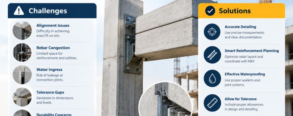
A panel is cast in a plant to tight limits, then set against a structure built to looser ones. Both can be within tolerance and still not line up. Haunch-to-haunch tolerances can run from 1/8 to 1/4 inch depending on the member, and the steel or cast-in-place work next to it has a range of its own.
Take a garage spandrel panel bearing on a ledge that was poured 3/8 inch low. That’s an ordinary variation. But if the seat has a fixed height and no shim allowance, the crew has two choices: grind the concrete or stack shims past their limit.
The solution
- Slotted or oversized holes in clip angles and plates
- Shim space at bearing points, with a cap on stack height
- Loose strap plates to bridge embeds that landed slightly off
- Slotted or coil-thread inserts where the field will need to adjust
However, the direction of the adjustment matters as much as the amount. A slot cut for horizontal shift won’t help when the elevation is off by half an inch. Precast panel shop drawings in the USA should state which way each connection gives and by how much, in inches.
Restrained movement
The challenge
Concrete shrinks, creeps, and moves with temperature. Hold a panel rigidly at every point, and those small movements build into large forces. The cracks then appear at the weakest spot, usually the embedment or the concrete around it. A tall cladding panel pinned at all four corners is the classic example.
The solution
Give each connection one job. Two bearing points carry gravity. Tiebacks handle wind and other out-of-plane loads, and they’re detailed to slide or flex in the remaining directions.
Therefore, that layout also makes review easier. A checker can point at the two bearing connections, then confirm that every other connection is free to move in at least one direction.
Thermal and seismic demands
The challenge
Insulated sandwich panels have inner and outer layers at different temperatures, and that difference pushes extra load into base and floor connections. In seismic regions such as parts of California and the Pacific Northwest, panels also have to ride out building drift.
The solution
- Sandwich panels: detail base and floor connections so the temperature difference between the layers doesn’t load the joint.
- Seismic zones: give connections ductility and movement capacity, and size the steel devices so they yield before a weld or the surrounding concrete does.
Weld access and weld heat
The challenge
Field welding to an embed plate looks easy on a plan. It looks different when the plate sits in a tight joint behind a neighboring panel, and the welder has to reach it from a lift. A crew that can’t see the weld will improvise, and improvised welds rarely match the design.
Additionally, heat is the second problem. Push too much of it into a plate anchored in concrete, and the concrete around it can crack or spall.
The solution
- Confirm on the drawings that a welder can physically reach each weld
- Specify plate thickness, weld size, and weld sequence so nobody has to guess
- Where a weld can’t be reached, switch to a bolted or otherwise accessible detail
Galvanized and stainless embeds
The challenge
Welding through galvanizing isn’t recommended. It gives off zinc fumes, and the uneven coating leaves a poor fit-up with cracks at the weld root. Stainless plates have their own problems. They expand more than carbon steel; they need special welder qualifications, and pairing them with carbon-steel rebar can set up galvanic corrosion.
The solution
Good precast concrete detailing services in USA spell out which areas get the coating removed before welding and how those areas are touched up afterward. For stainless, the drawings should note the welder qualification and keep stainless plates away from carbon-steel rebar where a galvanic couple could form.
Corrosion and exposure
The challenge
In northern states where road salt is common, parking structures show connection corrosion first. Salt reaches the joints, and freeze-thaw cycles widen any small crack. A coastal warehouse and an interior office building shouldn’t get the same coating spec, though they often do.
The solution
Match the protection to the exposure. The usual options run from shop primer to zinc-rich paint, metallizing, hot-dip galvanizing, epoxy and stainless steel, and cost climbs in roughly that order. Interior hardware may only need primer. Salt-exposed structures often justify galvanizing or stainless.
Threaded parts are usually electroplated instead, because galvanizing or epoxy can clog threads unless they’re re-tapped.
Moreover, the coating note also has to reach the field. Zinc-rich touch-up on welded areas only happens if the drawing names it, so put it in the weld note itself.
Clashes with other trades
The challenge
The cast-in-place structure is often designed and poured before the precast drawings begin, so slab edges, sleeves, and embeds are already fixed. Whatever doesn’t match becomes a site fix. Typical clashes:
- Anchor bolts set before the precast dimensions were final
- Embed locations that shift after the cladding attachments are chosen
- Façade brackets that can’t be reached once neighboring panels are up
- MEP penetrations added late, followed by coring into finished panels, which isn’t a safe fix
- Shim stacks and sealant depths that leave no room for the waterproofing detail
The solution
Coordinate embed and opening locations across the structure, cladding, and MEP trades before the drawings are released, and lock penetrations before casting. Precast concrete detailing services in the USA that review these interfaces early turn conflicts into questions on a drawing instead of changes in the field.
Erection sequence errors
The challenge
Say panel C has to go up before panel B for a bracket to be reachable, and nobody wrote that down. The crew finds out with a panel hanging from the crane.
Bracing causes similar trouble. A temporary brace can end up blocking the spot where the next panel’s connection has to be welded.
The solution
Check every connection against the erection order, not just the plan view. Put the order, lifting points, and temporary bracing on the drawings, and send them to the erector.
Wrong connection type and late changes
The challenge
No single connection fits every panel, and swapping types late, say from welded to bolted, changes stiffness and load path. Late changes are expensive for a simple reason. A drawing revision takes hours. A site fix takes a crew, sometimes a crane, and holds up the sealant and glazing crews waiting behind it. Redesigned embeds can even mean recasting a panel that’s already stored in the yard.
The solution
Sort every connection on a panel into a role first, bearing or tieback, and pick hardware after that. Precast panel detailing services in USA typically work in that order.
| Connection type | Where it works well | What the detailing must watch |
| Bearing (pad, corbel, haunch) | Beams, double tees, panels on foundations | Bearing length against long-term movement, shim limits |
| Welded plates | Panel to structure, blind joints | Weld access, heat, coating removal |
| Bolted with slots | Panels needing field adjustment | Slot direction, bolt access, hardware protection |
| Dowel or anchor bolt | Bases and columns | Dowel alignment within tolerance, grout pockets |
Any change of type goes back to the engineer of record. It also helps to repeat a small set of connections across the job, since fewer unique hardware pieces means less to fabricate and check.
A quick check before release
When you evaluate precast detailing services in USA, ask whether weld access and erection order are checked before release, how embeds get coordinated with steel and cast-in-place trades, and how revisions are tracked once fabrication starts. A firm like 12 Meter Engineering, which prepares precast detailing and shop drawing packages, works in the space between engineer, precast, and erector.
Therefore, you can also test any drawing set yourself. Pick three connections at random and ask whether a crew could reach each one, adjust it, and finish it in the order the panels arrive. If the answer to any of them is no, the sheet needs another pass.
Conclusion
Precast connection problems rarely announce themselves early. They show up as a small mismatch while a panel is hanging from a crane, and by then every fix costs time. Most of them have a drawing-stage answer.
If you’re choosing precast detailing services in USA, ask to see a sample connection sheet and read it the way an erector would: could a crew build from it without calling anyone? If you’re putting together a package for a current job, 12 Meter Engineering can review the connection sheets next to your engineer’s design before release, when a change is still cheap.
Frequently asked questions
Misaligned embeds, welds nobody can reach, no room for adjustment, corroded steel in exposed spots, and clashes with other trades. Most of them trace back to tolerances or erection order that never got checked on the drawings.
Two usual causes. Restrained shrinkage and temperature movement load the anchor zone, and heavy field welding can heat a plate enough to damage the concrete around it. Details that allow movement, plus controlled welding, reduce the risk.
Slotted or oversized holes, shim space, and loose connecting plates. Precast panel shop drawings in the USA should also list the adjustment range, so the erector knows how much correction is available.
Sometimes. Bolted types adjust easily but need bolt access and protection, and because stiffness and load path change, the engineer of record has to approve the swap.
It depends on the exposure, and the engineer specifies it. Interior hardware may need only a primer. Salt-exposed parking structures often justify galvanizing or stainless steel.
Connection layouts, embed locations, panel shop drawings, lifting and bracing information, and erection notes, all worked out from the engineer’s design and the precast plant’s practices.