Table of Contents
- Key takeaways
- What the PEB lifecycle covers?
- Design: loads, categories and site conditions
- Detailing: turning design into buildable drawings
- Fabrication: controlled work in the shop
- Erection: sequence, safety and tolerances
- Maintenance: keeping the frame sound
- Common mistakes across the lifecycle
- Final thoughts
- Frequently asked questions
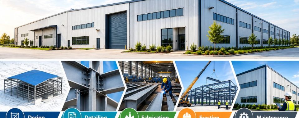
A pre-engineered building (PEB) undergoes 5 different stages before being finally constructed: planning, detailing, manufacture, erecting, and maintenance. The engineer calculates loads and determines the members’ sizes; the detailer prepares drawings for the workshop; the fabricator cuts, welds, and paints steel; the erection crew fastens it on site.
Moreover, maintenance keeps the exterior, light fittings, and roof in good shape for years. Structural steel detailing services in Australia occupy a central position in all these processes; thus, a mistake at this stage will revert back to the engineer and pass on to the site.
Key takeaways
- Design in each PEB stage is interrelated, with the decisions made in each influencing the detailing, fabrication, erection, and maintenance process.
- In Australia, PEB projects follow the standards AS 4100, AS/NZS 1170.2, and AS/NZS 5131.
- Problems experienced at the site can often be avoided or caused at the detailing stage of PEB construction.
- Decisions made during the selection of the coating, drainage, and roof access systems define the maintenance requirements of the PEB afterwards.
What the PEB lifecycle covers?
A PEB is a steel building where the frame, secondary members and cladding are designed together and made off site. The primary frame is normally tapered, built-up columns and rafters, deeper where bending is highest and slimmer where it isn’t. Purlins and girts run between the frames and carry the roof and wall sheeting.
Here’s how the work passes from one party to the next:
| Stage | What gets produced | Main owner |
| Design | Load calculations, frame sizing, footing reactions | Structural engineer |
| Detailing | General arrangement, shop and erection drawings, bolt lists | Detailer |
| Fabrication | Marked, welded, coated members | Fabricator |
| Erection | Plumbed frame, secondary steel, cladding | Erector |
| Maintenance | Inspection records, repairs | Owner or facility manager |
Every hand-off loses a little information. Take a 60 m by 30 m distribution shed designed on 6 m bays. Midway through, the tenant changes the dock layout and one door opening moves. If nobody tells the engineer, the frame that turns up on site may not fit the building that’s actually being built.
Design: loads, categories and site conditions
Design starts with what the building has to carry and where it will stand. AS/NZS 1170.2 splits Australia into wind regions A to D, and C and D are cyclonic. Put the same shed in a cyclonic region and the engineer changes the sections, the footings and the cladding fixings, so it takes more than bigger bolts. Internal pressure gets its own check too. If a roller door gives way in a storm, the pressure inside the building jumps, and the frame has to survive that case.
Wind region is one input among several. The engineer also needs:
- Terrain category, height, shielding and topography of the site
- Roof and floor loads, including crane runways, mezzanines and rooftop solar
- Clear span, eave height, bay spacing and door positions
- Corrosion exposure, which is much harsher near the coast
- Any planned extension, so the end wall can be made ready to open up later
Furthermore, then comes the construction category under AS/NZS 5131, from CC1 (lowest risk) to CC4 (highest). Farm sheds sit near the bottom. Low to medium-rise industrial buildings usually land in CC2. The category has real consequences, because it sets how much inspection, testing and traceability the fabricator must show. Where a site is bushfire prone, AS 3959 adds requirements for cladding, vents and eaves.
Detailing: turning design into buildable drawings
Engineering drawings show design intent. They don’t tell a workshop where every hole goes or how big each weld is. Detailing fills that gap with:
- General arrangement plans and anchor bolt setout
- Frame elevations and connection details
- Assembly and part drawings with mark numbers
- Bolt, cutting and material lists
- Erection drawings that tie every mark to a location
Steel detailing services in Australia usually work from three documents at once:
- The engineer’s package
- The architect’s layout and the site survey.
- A careful detailer reads them side by side.
That’s how you find a purlin cleat fouling a rafter flange, or an anchor bolt pattern that hits the slab reinforcement. Splice positions get checked against trailer lengths and crane capacity too, since a perfect frame that can’t be trucked in is no use to anyone.
Therefore, a detailing team such as 12 Meter Engineering works at this stage, comparing the engineer’s drawings with site and workshop constraints before any steel is cut. Structural steel detailing services in Australia also carry local requirements down to the drawing level. Bolt grades, weld categories, coating notes and the construction category belong on the drawings themselves, not buried in a separate specification.
Most detailers build a coordinated 3D model and pull the 2D drawings from it. The model shows clashes early, though it can’t judge everything. Somebody still has to ask whether a normal wrench actually fits into the connection.
Fabrication: controlled work in the shop
The shop works in a fairly fixed order:
- Cutting
- Drilling or punching
- Fit-up, welding
- Surface preparation
- Coating
- Marking and packing.
Drawings drive every step, so a vague drawing produces a vague part.
If you’re comparing steel fabrication drawings services in Australia, look at whether the drawings state weld sizes and types, bolt grades, surface preparation and the coating system. The mark numbers should match the erection plan exactly. When they don’t, the shop and the site end up working from two different descriptions of the same building.
Additionally, welding is usually governed by AS/NZS 1554. Coating follows corrosion exposure: AS 4312 classifies atmospheric corrosivity, and the coating system is chosen from that. Hot-dip galvanising to AS/NZS 4680 suits coastal and other harsh sites, but all drilling and welding has to be finished before the dip, so late changes hurt. Painted systems are easier to alter and touch up, at the price of a planned repaint cycle.
AS/NZS 5131 matters most when steel is imported. Overseas fabricators need to show they meet it, and for CC2 to CC4 that includes baseline traceability of materials. A CC1 farm shed gets a lighter touch. For a CC2 factory, ask to see the inspection and test plan before you award the package.
Erection: sequence, safety and tolerances
Erection really starts before the first crane lift. Anchor bolts and base levels are checked against the drawings, since a few millimetres of error at a base plate can stop a column from standing plumb. Fixing that on site costs far more than checking it first.
After that the sequence runs roughly like this:
- Erect and brace the first bay so it stands on its own.
- Lift the remaining frames, adding bracing as each one goes up.
- Fit purlins and girts, then check plumb and line.
- Tighten the bolts by the specified method.
- Install roof sheeting, wall cladding, flashings, gutters and doors.
Wind is a genuine risk mid-erection. A half-braced frame is much weaker than the finished building, so temporary bracing and weather limits belong in the erection plan, along with lift plans, exclusion zones and fall protection for work at height.
Therefore, when you compare steel erection drawings in Australia, look for frame lines, member marks, orientation arrows, piece weights, bolt counts and the order of installation. A crew shouldn’t have to guess which end of a rafter goes where.
Maintenance: keeping the frame sound
A PEB needs little upkeep, but it does need some, and most problems start small and at the edges. A practical routine looks like this:
- Inspect at least once a year and after any severe storm
- Check roof and wall fixings, sealants and flashings for loosening or wear
- Clear gutters and downpipes, since standing water attacks coatings and fixings
- Look closely at cut edges, laps and bolt heads, where coating damage usually starts
- Near the coast, wash down sheltered surfaces such as eaves and soffits, because rain never reaches the salt that collects there
- Touch up damaged coating early, before rust creeps under the paint
How often to repaint depends on the site’s corrosivity, so there’s no single interval that suits every building. Keep the drawings and inspection records together. If the owner later adds a mezzanine, rooftop solar or a new opening, the engineer should check the frame first, because those changes alter the loads the building was designed for.
Common mistakes across the lifecycle
- Settling wind region and terrain assumptions late, after member sizes are already fixed
- Freezing drawings before doors, crane loads and services are confirmed
- Treating the construction category as a formality
- Placing splices without thinking about transport and lifting limits
- Leaving out an access plan for cleaning gutters and inspecting the roof
- Adding loads years later with no structural check
Final thoughts
If you’re planning a PEB, settle the site conditions, loads and any future changes early, and keep the engineer, detailer and fabricator working from the same information. Before steel is ordered, get the construction category, the coating system and the drawing checks in writing. Bringing in structural steel detailing services in Australia before the drawings are frozen costs little.
Moreover, the same change after fabrication starts means cutting, welding and re-coating steel that already exists. Once the building is handed over, keep the inspection records with the drawings so the next owner or engineer can see what was built and how it has aged.
Frequently asked questions
Design decides what the structure must resist and sizes the members. Detailing decides exactly how each piece is cut, connected and marked so it can be made and assembled.
Commonly AS 4100 for steel design, the AS/NZS 1170 series for loads, AS/NZS 5131 for fabrication and erection, AS/NZS 1554 for welding, and the National Construction Code for building requirements.
Yes. Steel detailing services in Australia exist because engineering drawings show design intent, not every hole, weld and mark number a workshop needs.
Member sizes, weld types and sizes, bolt grades, surface preparation, the coating system and mark numbers. Steel fabrication drawings services in Australia should also link each part to the erection plan.
Frame lines, member marks, orientation, piece weights, bolt counts and installation order. Good steel erection drawings in Australia let a crew follow the sequence without phoning the office.
Yes, if it was planned for. An end wall frame can be designed to be replaced by a full frame, but the original footings and members must be able to carry the added load.
Galvanising suits coastal and harsh sites and needs less upkeep. Paint is easier to modify and touch up. Let the site’s corrosivity category decide.