Table of Contents
- Key takeaways
- What makes PEB engineering different from conventional steel construction?
- Common design challenges in industrial PEB projects
- Why does detailing accuracy decide whether a PEB project stays on budget?
- PEB vs conventional steel structures: A side-by-side comparison
- Best practices for reliable PEB design and detailing
- Mistakes that show up most often in industrial steel projects
- How does the right detailing partner change the outcome?
- Conclusion
- Frequently asked questions
Key takeaways
- The accuracy of load paths, connection design, and structural detailing is highly important for PEB projects.
- Inefficient detailing leads to expensive delays and rework as well as unrepaired connections during the process of steel erection.
- All mistakes can be detected with the help of specialized fabrication and erection drawings before initiating production of the steel.
- Acquiring professional structural steel detailing services in the USA ensures enhanced efficiency and improved project timelines.
Anyone who has managed an industrial steel project knows there’s a gap between a clean structural design and a building that actually goes up without drama. Pre-engineered buildings are supposed to close that gap. They’re standardized and faster to fabricate than conventional structures. That efficiency only holds, though, if the detailing behind the design is done right.
A warehouse frame that looks fine in the analysis model can still fail at fabrication if bolt patterns don’t match, if a purlin lap conflicts with a bracing rod, or if nobody thought through the erection sequence before drawings went to the shop. Structural steel detailing services in the USA earn their keep here. Detailing isn’t a formality tacked onto engineering. It’s the layer that turns a structural concept into steel that can actually be built.
This article walks through the design challenges specific to PEB projects for industrial buildings, and the detailing practices that keep those projects on schedule and on budget.
What makes PEB engineering different from conventional steel construction?
PEB systems rely on tapered built-up sections instead of standard hot-rolled shapes. The profile of the steel corresponds to the bending moment diagram, meaning that the sections of the steel are thickest at the point of maximum load, thus using material efficiently. However, this also means that all connections will need to be designed for the specific profile being used. Connections cannot be designed based on the standard tables.
Therefore, conventional steel construction uses standard rolled sections with connections that follow well-established codes and repeatable patterns. PEB doesn’t have that luxury. Every frame is essentially custom, sized to the building’s span, bay spacing, and loading, which is a big part of why detailing for PEB structures takes more coordination than people expect going in.
Additioally, industrial buildings also have their complexities. They need to factor crane loads, mezzanines, equipment vibrations, and niche inclusions in the frame designs, and it’s not as straightforward as it seems. The design of the frame has to be done precisely, or it may turn out to be either overbuilt and waste steel or underbuilt, making it unsafe.
Common design challenges in industrial PEB projects
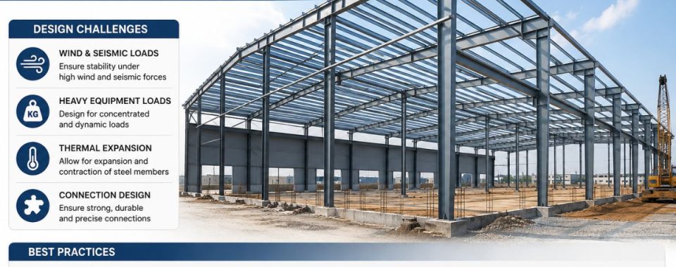
- Load Path Assumptions That Don’t Match Site Conditions
A lot of PEB design software assumes idealized support conditions. In practice, foundation stiffness, soil bearing capacity, and anchor bolt layout can all differ from what the model assumes. If the detailer doesn’t flag this early, the anchor bolt plan sent to the foundation contractor might not match what the steel frame actually needs.
- Crane Runway Integration
Industrial buildings with overhead cranes need runway beams that handle both vertical loads and lateral thrust from crane operation. Get the runway bracket connections wrong, even by a small tolerance, and you get operational problems once the crane is running. This is one area where steel detailing services in USA teams spend a disproportionate amount of review time, because the margin for error is small.
- Mezzanine and Secondary Framing Conflicts
Mezzanines added later in the design process often clash with primary frame bracing or purlin spacing. If detailing happens after the mezzanine layout is locked, changes ripple through dozens of connection drawings.
- Wind and Seismic Load Variability
Industries building construction, and particularly tall buildings which utilize a lot of steels for the structures, are susceptible to wind action and earthquakes. Laws governing the construction industry vary according to the states due to the different winds across states, hence, the structure built in one location cannot be transported to another location. That happens more often than people admit.
Why does detailing accuracy decide whether a PEB project stays on budget?
Design errors caught on paper cost almost nothing to fix. The same error caught after steel is fabricated costs real money and real time. That’s the core argument for investing properly in structural steel detailing services in USA instead of treating detailing as a rubber stamp after engineering signs off.
A detailing team working from accurate 3D models can catch clashes between purlins, girts, bracing rods, and flange braces before a single plate is cut. They also produce the fabrication drawings that shop workers actually use, and the erection drawings that field crews follow to sequence the build.
Moreover, when detailing gets rushed, or gets handed to a low-cost team without much project context, the same problems tend to surface. Bolt holes that don’t align because nobody checked connection geometry against actual member sizes. Erection sequences that assume site access or crane positioning that doesn’t match reality. Weld symbols left off or wrong, forcing fabricators to guess at intent.
These aren’t hypothetical. They’re the recurring complaints from steel erectors on jobs where detailing was treated as an afterthought.
PEB vs conventional steel structures: A side-by-side comparison
| Factor | PEB Structures | Conventional Steel Structures |
| Member type | Tapered built-up sections | Standard hot-rolled sections |
| Design flexibility | Optimized for standard bay spacing | More flexible for irregular layouts |
| Fabrication speed | Faster, factory-controlled process | Slower, more manual shop work |
| Detailing complexity | High, connections are project-specific | Moderate, more repeatable connection types |
| Cost efficiency | Strong for repetitive spans | Better for complex or non-standard geometry |
| Common use cases | Warehouses, factories, distribution centers | High-rises, bridges, irregular industrial layouts |
Neither system is universally better. It comes down to span requirements, whether the client expects to expand later, and how much architectural flexibility the project actually needs.
Best practices for reliable PEB design and detailing
- Model in 3D from the start- Clash detection between purlins, bracing, and mezzanine framing is far easier to catch in a coordinated 3D model than in isolated 2D drawings. Teams that skip this step usually find the conflicts on-site instead, which is a worse place to find them.
- Lock the anchor bolt plan early- Foundation work often starts before steel fabrication finishes. If the anchor bolt layout changes after the foundation is poured, that’s an expensive fix. Coordinating this between structural engineers and the foundation contractor before concrete goes down avoids the problem entirely.
- Separate fabrication drawings from erection drawings- Shop fabricators need piece-level detail, tolerances, and weld symbols. Field crews need sequence, bolt-up order, and temporary bracing notes. Combine the two into one set, and neither group gets what it actually needs.
- Build in tolerance for site variability- Real foundations are never perfectly level, and real steel has mill tolerances. Detailing that assumes zero deviation creates fit-up problems during erection.
- Review crane runway connections on their own- These are sensitive enough to load and fatigue that they deserve a separate check, outside the general connection review.
Furthermore, teams that provide structural steel detailing services alongside steel structure erection drawing service in USA, rather than splitting the two across vendors, tend to catch coordination issues earlier. Simply because the same people are looking at both ends of the process.
Mistakes that show up most often in industrial steel projects
Rework on industrial steel jobs almost always traces back to the same handful of causes:
- Purlin laps that weren’t checked against the final roof slope, causing field cuts
- Bracing rods sized without accounting for actual connection eccentricity
- Erection drawings that don’t match the final revision of the fabrication drawings
- Anchor bolt projections that don’t match the base plate hole pattern
- Missing coordination between mechanical, electrical, and structural openings in the frame
Most of these aren’t engineering failures. They’re coordination failures, gaps between design intent and what actually gets drawn, cut, and shipped. That’s the gap that thorough steel fabrication drawings services in USA are meant to close, and it’s why experienced detailers spend so much time cross-checking drawings against each other, not just against the design model.
How does the right detailing partner change the outcome?
The difference between a smooth PEB project and a delayed one usually isn’t the design software, or even the engineering firm. It’s whether the detailing team understands fabrication shop workflows and field erection realities, not just how to produce technically correct drawings.
12 Meter Engineering handles this coordination directly, connecting structural design intent to fabrication-ready and erection-ready drawing packages so what gets modeled is what gets built. For industrial clients juggling tight schedules and multiple trades, that continuity between design and detailing tends to matter more than any single software feature.
Conclusion
PEB engineering rewards precision. The systems are efficient by design, but that efficiency depends on detailing that accounts for real fabrication tolerances, real site conditions, and real erection sequencing, not just a clean structural model. Industrial buildings raise the stakes further with crane loads, mezzanines, and code requirements that shift from state to state.
Getting this right isn’t about adding review steps for their own sake. It’s about having a detailing process that catches the specific problems PEB structures tend to produce before they turn into field rework. If your next industrial project needs that level of coordination, reach out to 12 Meter Engineering to talk through your drawing package requirements.
Frequently asked questions
PEB engineering is used for warehouses, factories, distribution centers, and other industrial buildings that need large clear spans and fast, cost-efficient construction using tapered steel frames.
PEB uses tapered built-up sections optimized for specific loads, while conventional steel construction uses standard rolled sections with more repeatable, code-based connections.
Fabrication drawings give shop workers exact piece dimensions, tolerances, and weld details. Without them, fabricators have to guess at intent, which leads to rework and delays.
Delays usually come from clashes between purlins, bracing, and secondary framing, or from erection drawings that don’t match the final fabrication revision.
Yes, but crane runway beams and their connections need separate engineering checks for lateral thrust and fatigue, since these loads behave differently from standard gravity loads.
As soon as the structural design is reasonably firm, ideally before foundation work begins, so anchor bolt layouts are locked before concrete is poured.
Fabrication drawings guide shop cutting and welding. Erection drawings guide field crews on assembly sequence, bolt-up order, and temporary bracing during construction.
Yes, with proper design. Wind and seismic loads vary by state, so frames need to be engineered for the specific site, not reused from a different region’s design.
A team experienced in both fabrication and erection workflows, not just drawing production. That’s what actually prevents most on-site fit-up issues.
Yes. It catches physical clashes between structural members that are easy to miss in 2D drawings, which is one of the most common sources of field rework.