Table of Contents
- Key takeaways
- Why does connection design determine the life of a PEB structure?
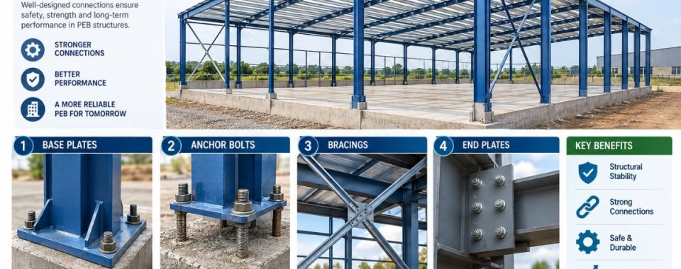
- Base plates: the foundation interface
- Anchor bolts: holding the frame in place
- Bracings: managing lateral and wind loads
- End plates: connecting rafters and columns
- Common mistakes in PEB connection design
- Expert insights from the field
- Conclusion
- Frequently asked questions
Key takeaways
- Base plates transfer loads from columns to foundation, and they need to be checked for bearing pressure and bolt spacing.
- Depth of the cement in anchor bolts is often what separates the successful building frame from the expensive failure.
- Bracing takes care of lateral sway and wind loads, particularly in industrial buildings with open space.
- End plate connections should correspond with the rotational stiffness assumptions in the analysis of the structure; otherwise, it will not behave according to the plan.
Pre-engineered buildings look simple from the outside: straight columns, sloped rafters, a clean frame. The connections holding that frame together are where most structural problems actually start. An undersized base plate. An anchor bolt that’s too shallow. An end plate that doesn’t match the moment it’s supposed to carry. Any one of these can turn a well-designed building into a liability. Getting connection design right means understanding how loads actually move through a PEB frame, not just pulling a standard detail off the shelf.
Why does connection design determine the life of a PEB structure?
A PEB frame is only as good as the joints connecting its members. The primary steel- columns, rafters, purlins- gets most of the attention during design review, but the connections carry the actual stress concentrations. Every load path in a pre-engineered building eventually funnels down to a handful of bolted or welded joints. If those joints are miscalculated, the whole system is compromised no matter how strong the members themselves are.
However, accurate structural steel detailing services in USA projects matter here because detailers translate the engineer’s design intent into fabrication-ready drawings. A small error at this stage- a mis-sized bolt hole, a wrong plate thickness- can cascade into rework, delays, or an unsafe connection on site.
Base plates: the foundation interface
The base plate sits between the steel column and the concrete foundation, spreading the column’s axial load, shear, and moment across a wider bearing area than the column section alone could handle. Concrete has a much lower bearing capacity than steel. Without a properly sized plate, the column would eventually punch through the foundation.
Base plate design depends on a few interacting factors:
| Factor | What It Affects |
| Column load (axial + moment) | Plate thickness and bearing area |
| Concrete compressive strength | Allowable bearing pressure |
| Anchor bolt pattern | Plate dimensions and edge distances |
| Grouting method | Load transfer uniformity |
A plate that’s too thin will deflect under load and create uneven bearing stress, which over time can crack the surrounding concrete. Detailers working from the engineer’s calculations size the plate thickness using yield line theory or simplified cantilever methods, depending on the bolt layout and load eccentricity.
Here’s something that trips up a lot of first-time PEB contractors: base plates for moment connections, fixed-base columns, need to be noticeably thicker and have wider bolt spacing than pinned-base plates, because they’re resisting rotation and not just vertical load. Treating every base plate as a standard pinned connection is a shortcut that catches up with people during erection.
Anchor bolts: holding the frame in place
Anchor bolts tie the base plate, and by extension the entire steel frame, into the concrete foundation. They resist uplift from wind suction, shear from lateral loads, and in moment connections, they help resist the overturning moment at the column base.
Moreover, embedment depth is the single most important variable here. Too shallow, and the bolt can pull out of the concrete under uplift before the steel itself yields. That’s a brittle, sudden failure mode, and engineers go out of their way to avoid it. Required depth depends on:
- Bolt diameter and grade
- Concrete compressive strength
- Edge distance and spacing from adjacent bolts
- Whether the bolt is cast-in-place or post-installed
Post-installed anchors, epoxy or mechanical, show up often on retrofit or addition projects where the foundation was poured before final column loads were confirmed. They work fine when installed correctly, but they need tighter quality control. Drilling depth, hole cleaning, and cure time all matter more than people expect.
One practical note from experience: anchor bolt templates need to be checked against the actual base plate hole pattern before the foundation is poured, not after. Sounds obvious, but bolt pattern mismatches between the civil contractor’s template and the steel detailer’s drawing are one of the most common, and most expensive, coordination failures on PEB jobs.
Bracings: managing lateral and wind loads
Bracing keeps a PEB frame from swaying or racking under lateral forces, whether that’s wind, seismic activity, or crane loads in industrial buildings. Without it, a steel frame is basically a series of hinges that can shift sideways with very little resistance.
There are two main bracing categories in PEB structures.
- Wall bracing- uses rod or cable bracing in the wall panels, usually in an X-pattern, to resist longitudinal wind and seismic forces along the building length.
- Roof bracing- sits in the roof plane and transfers wind loads from the end walls into the main frames, keeping the roof diaphragm stable during lateral events.
The bracing layout follows the wind load path calculated during the primary design phase; it isn’t arbitrary. Bracing placed without regard to the actual load path can leave some bays under-braced while others carry more force than intended. This shows up clearly in accurate steel erection drawings in USA projects, where bracing bay locations, rod sizes, and turnbuckle details need to be unambiguous for the erection crew.
One mistake worth flagging: swapping the specified cable or angle bracing for rod bracing without re-checking the connection capacity. Different bracing types transfer force differently at the gusset plate, and switching materials mid-project without engineering sign-off can quietly undersize a connection that looks fine on paper.
End plates: connecting rafters and columns
End plate connections join the rafter to the column, or splice one rafter section to another, typically at the ridge or at knee joints. These are moment connections in most PEB frames. That means they transfer bending moment, shear, and axial force at the same time, not just hold two members together.
Plate thickness, bolt diameter, and bolt row spacing all get calculated based on the moment the connection needs to resist. A thicker plate with more bolt rows carries a larger moment, but it also adds weight and cost, so there’s a real trade-off engineers work through during design.
Furthermore, two details matter more than people initially assume. Stiffener plates are often added near the flange-bolt rows to keep the end plate from bending excessively under tension, which would otherwise cut into the connection’s stiffness. And bolt pretension has to match the specified value, snug-tight or fully pretensioned depending on the connection classification, because under-tightened bolts in a moment connection can slip and rotate unexpectedly under load.
This is another area where precise shop drawings services in USA fabrication shops depend on to cut and drill plates correctly the first time. A discrepancy of even a few millimeters in bolt hole location on an end plate can stop field bolt-up cold, forcing on-site rework that no contractor wants during erection week.
Common mistakes in PEB connection design
- Ignoring eccentric loading at base plates, assuming a purely axial load when the column actually carries moment from wind or crane action.
- Undersized anchor bolt embedment, often the result of trying to keep foundation depth shallow to save concrete cost.
- Bracing rod sizes copied from a similar past project without re-verifying against the specific wind zone and building geometry.
- Mismatched bolt grades between the design drawings and what’s actually procured for the site, a gap that’s more common than it should be.
- Skipping stiffener plates on end plates to save fabrication time, which weakens the connection’s actual moment capacity.
Expert insights from the field
Most connection failures I’ve seen aren’t really engineering failures. They’re a gap between the calculated design and what actually gets fabricated or installed. A base plate calculation can be correct on paper and still fail in the field if the anchor bolt template shifts an inch during the concrete pour. That’s why coordination between the structural engineer, the detailer, and the erection crew matters just as much as the calculations themselves.
Firms offering structural steel detailing services in USA markets that also cross-check shop drawings against the original engineering calculations, not just against fabrication standards, tend to catch these mismatches before steel ever reaches the site. It’s a small extra step, and it saves real rework cost later.
Conclusion
Connection design is where PEB engineering holds up or falls apart. Base plates, anchor bolts, bracings, and end plates each carry a specific role in the load path. Treating any of them as a standard detail without checking the actual project conditions is where problems start. Getting these right the first time comes down to close coordination between design, detailing, and fabrication teams.
If you’re working on a PEB project and want connection details that hold up from design through erection, 12 Meter Engineering works closely with engineers and contractors to get base plates, anchor bolts, bracings, and end plates detailed accurately from the start.
Frequently asked questions
A pinned base plate resists only axial and shear loads. A fixed base plate also resists moment, which is why it needs a thicker plate and wider bolt spacing.
It depends on bolt diameter, concrete strength, and uplift force, and the structural engineer calculates it. There’s no universal depth that fits every project.
Bracing resists lateral forces like wind and seismic loads and stops the frame from swaying or racking, since a PEB frame alone offers little resistance to sideways movement.
Not without engineering approval. Different bracing materials transfer force differently at the connection, and swapping one for another can undersize the joint.
Most trace back to under-tightened bolts, missing stiffener plates, or bolt hole misalignment between the design drawing and the fabricated plate.
Because accurate calculations can still fail in the field if fabrication or foundation work doesn’t match the design drawings. Coordination is what prevents that.
They limit excessive bending of the end plate under tension, which helps the connection keep the stiffness assumed during the frame’s moment analysis.
Yes, when installed with proper drilling depth, hole cleaning, and cure time, though they need tighter quality control than cast-in-place anchors.
From the column’s axial load, moment, and bolt pattern, usually using yield line theory, balancing bearing pressure against plate deflection.
A mismatch between the anchor bolt template used during the concrete pour and the actual base plate hole pattern from the steel drawings.