Table of Contents
- Key takeaways
- What are precast erection drawings?
- What information do precast erection drawings contain?
- Why do erection drawings matter for site installation?
- Key benefits of accurate erection Drawings
- How do erection drawings connect with fabrication and panel detailing?
- What problems do inaccurate drawings cause?
- Best practices for reliable erection drawings
- Quick reference table: drawing information and site impact
- Conclusion
- Frequently asked questions
The precast erection drawings provide the site crew with essential information regarding the placement, orientation, lifting technique, and fastening methods used for each panel. When these drawings are correct, the panels arrive in the desired order and installation becomes simple and efficient. 12 Meter Engineering’s precast detailing service converts the design intent into usable drawings that allow fabricators and erectors to build.
However, the success of a precast project lies in the difference between the casting plant and the site. The panels are produced days ahead of their installation, sometimes in a different city, and by people who will never see the slab. Erection drawings bring the two places together.
Key takeaways
- Erection drawings help in the field. Shop drawings assist at the plant.
- Marks for the pieces, how they are oriented, and the order in which they must be placed will help prevent mistakes.
- Details of connections, embeds, and lifting devices must be as per what has been cast.
- Coordination of the detailer, precast, and erector very early helps save more time than anything that is done at the job site.
What are precast erection drawings?
Erection drawings, referred to as erection plans as well, illustrate how precast concrete panels and other components are put together. They serve as guides for the crane operators and field supervisor.
This is different from fabrication drawings. Fabrication drawings show you how an individual part is created; that is, its shape, reinforcing, and the hardware within. Erection drawings present the details of how the pieces fit together; that is, where they sit and how they are secured.
To put it another way, one element reveals how to assemble components, while the other gives instructions on putting the pieces together to build the building.
What information do precast erection drawings contain?
A full set of answers is provided without the need to phone in questions by an erector. Typically it includes:
- Panel layout and piece marks: A plan and elevation of each panel with a different mark on them which corresponds with the mark cast into or tagged on the panel.
- Measurements and coordinates: Panel width, height, and location aligned to building grid lines and finished floors.
- Orientation: Which face is the outside and which edge is the top face, and which end is towards which grid line. This is important for many almost symmetrical panels.
- Connection details: Welded plates, bolted angles, grout tubes, dowels or loop bars, and hardware required on each side.
- Use plates and cast-in materials: Position and type of hardware used for connections to the structure for panels.
- Information relating to lifting and handling: The location of the lifting points, rigging notes, and any stripping and tilting information that may be required.
- Joint information: Joint widths, sealant and backer rod notes, and reveal or drip.
- Tolerances: Tolerances for plumbness, alignment, and joint width, generally based on industry tolerance guidance provided by PCI.
- Erection sequence: The sequence of setup, temporary bracing, and when it can be removed.
Not all the items are required in each project at the same level. However, a simple wall panel job may require a simpler set than a multi-story parking structure that has spandrels, columns, and double tees. That is, there should be no room for guesswork by the crew in what they need to do.
Why do erection drawings matter for site installation?
Setting a precast panel is a high-consequence work activity. Each piece may weigh tons and is being lifted by a crane, with workers helping to maneuver it into position. Little flexibility for improvisation.
A good drawing allows the crew to plan ahead of the first truck. They understand the sequence of panels to install, crane location, room requirements for rigging, and availability of temporary bracing. All of the above is underscored by the OSHA rules on precast erection (29 CFR 1926 Subpart Q), which place a new emphasis on proper lifting equipment, controlled movement, and bracing, and clear erection documentation reinforces this.
Additionally, there’s also a scheduling reason. Crane rental and crews are very costly per hour. If a panel does arrive and no one can determine which end is up, the entire crew waits.Precast Panel Detailing Services in USA can be helpful in such matters.
Key benefits of accurate erection Drawings
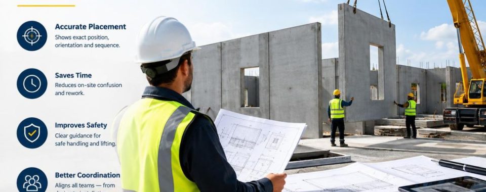
- Fewer setting problems, like panels flipped or placed in an incorrect location.
- Fewer connection rework due to hardware and clearances being verified.
- More consistent crane time and delivery sequence.
- Safer lifts, as rigging and bracing details are recorded and not taken for granted.
- Easier dialog between the precast, erector, general contractor, and engineer of record.
- Faster inspection and closeout, as-built conditions can be compared against a clear reference.
How do erection drawings connect with fabrication and panel detailing?
These three pieces of work are interrelated, and the lack of strength in one is manifesting in the other.
- The process of designing each precast panel in detail, including geometry, reinforcement, embeds, lifting hardware, finishes, and openings, is called panel detailing. That information is carried forward into the documents that are used by the plant and the field by Strong Precast Panel Detailing Services in the USA.
- Detailed panels are then used in fabrication drawings to package them for production. Precast fabrication drawings services in USA guarantee that all embed plates, block-outs, and reinforcing bars are positioned where the form crew can see them.
- The finished panels are assembled into a building in erection drawings. The erection drawings bring the finished panels back together as a building. The erection drawing shall be updated if a panel was changed during the detailing, such as an embed moved or a window opening changed. If not, the field gets one thing, and the plant makes some other.
Furthermore, the cleanest projects see these as an integrated project, not three discrete projects. This is also partly why many teams opt for precast erection services USA that are knowledgeable in the drawing side and the way a crew sets panels.
What problems do inaccurate drawings cause?
The majority of site issues can be traced to a few drawing issues. Common ones include:
- Piece marks that do not match between the shop drawings and the erection plan.
- Reversed panels due to missing or unclear orientation.
- Embed locations in which there are differences between panel and supporting structure.
- Hardware for connections that conflicts with reinforcement or adjoining panels.
- Lifting points that do not have enough information regarding rigging angles and panel balance.
- Joint widths that do not take into account tolerance build-up over a long elevation.
- Note that they ignore when the crane is placed, delivery order, and stability when set.
- Revisions that make it to the plant, but not to the field set.
They are all relatively small in size. In the field, each can stop a lift, cause a field modification, or generate a request for information that can take days to answer.
Best practices for reliable erection drawings
There are some similarities in the habits of strong drawing packages.
- Begin with trusted information: Verify architectural and structural drawings, grid lines, and floor elevations before beginning detailing.
- Consistently use piece marks: Apply the same marking convention to layout, shop, and delivery tags.
- Show orientation clearly: Arrows, face labels, north references, eliminate doubt.
- Detail connections with both ends in mind: The panel hardware along with the structure hardware should be examined together.
- Add lifting and bracing indications: Indicate locations of lifting points and make note of any special rigging or temporary support requirements.
- Use the erector to plan the sequence: They sometimes have a keen eye to see crane reach, access, and staging problems early in the field.
- Control revisions: Clear revision clouds, dates, and a single issue log to prevent working from an outdated sheet.
- Run a coordination check before release: Verify that all dimensions of embeds, openings, joints, and tolerances are consistent for all types of drawings.
Quick reference table: drawing information and site impact
| Information in Erection Drawings | How It Helps Site Installation |
| Piece marks and panel layout | Crew identifies each panel and its exact location quickly |
| Grid references and dimensions | Panels are positioned accurately against the building frame |
| Orientation notes | Prevents reversed or rotated panels |
| Connection details | Shows what hardware to weld, bolt, or grout and in what order |
| Embed plate locations | Confirms where the panel meets the structure |
| Lifting points and rigging notes | Supports safer, balanced lifts and correct rigging setup |
| Joint widths and sealant notes | Keeps alignment and weatherproofing consistent |
| Tolerances | Gives the crew a clear acceptance standard |
| Erection sequence | Reduces crane moves, delays, and stability risks |
| Temporary bracing information | Keeps panels stable until permanent connections are complete |
Conclusion
Precast construction relies on the manufacturing of its products at one location and their installation at another place. The entire process is guided by erection drawings that contain information about locations, connections, orientations, logistics, and all sequencing, ensuring that the operation at work remains organized and safe.
High-quality drawings minimize redoing the job, avoid schedule issues, and make the crane work more predictable than it has ever been. They also make the work of all the people engaged in the process, from detailers to erectors, much easier.
If you require trustworthy precast detailing services in USA, you can rely on 12 Meter Engineering, which provides contractors, erectors, and manufacturers with detailed drawings that reflect the real conditions on-site.
Frequently asked questions
Shop drawings depict how every precast component is constructed. Erection drawings give information on how the finished component is attached to the building.
The construction workers, crane operators, site managers, and contractors all use this technique in their work, and so do inspectors checking the work.
At least, the drawing should show the piece mark, position, orientation, connection type, embed position, and lifting.
It connects the precast piece in the yard to where it shall be on the drawing. If the marking is incorrect, a wrong precast piece may be loaded onto the crane.
Typically, lifting points and handling instructions are indicated. The rigging design can come from the precast fabricator or from a separate engineer, depending on the situation.
The tolerances set the range of acceptable variations. If these tolerances are vague, some panels may be rejected or adjusted too much unnecessarily.
Some of the causes of delays are unclear orientation, hardware problems, omitted embeds, sequence conflicts, and outdated drawings.
Yes, it is possible to outsource detailing as long as the detailer knows the practices in the U.S., PCI guidelines, and the local needs. The communication between the precast and erector, as well as the proper timing, is crucial.