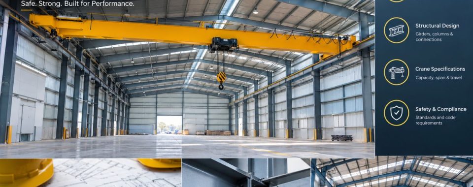
In a PEB structure, the crane load design involves calculation and resistance of forces exerted on a building’s frame, runway beams, columns and foundations by overhead cranes. Pre-engineered buildings are optimized for weight and speed, which allows crane forces to control member sizes if not planned.
In this blog, we will describe the different types of load and how one may calculate it, as well as the loading norms in Australia and how detailed drawings become a reality. The provided basics are of great help to engineers, manufacturers, and owners because they will help in the prevention of any unnecessary redesign.
Key takeaways
- Crane loads are often the determining factor for column, rafter, and bracing sizes in PEB structures and are therefore a consideration from concept.
- Vertical, lateral, and longitudinal forces should all be calculated, and the dynamic effects should be taken into account via an impact factor.
- To ensure safe crane operation, accurate connection, bracing, and runway beam restraint is critical.
- Fabrication errors and delays on site are minimized through the use of clearance erection drawings and shop drawings.
What is crane load design in PEB structures?
Crane load design for PEB structures involves the calculation of the forces that overhead cranes pass to the building frame, runway system, and foundations. These forces are coupled with wind forces, seismic forces, and other building loads, so that each member and connection can safely work for the entire life of the crane.
In pre-engineered buildings, light frames, tapered built-up sections and standardised connections all help to keep the tonnage of steel to a minimum. Crane loads, however, are dynamic, repeated and concentrated. They can also override the roof and wall loads assumptions, so it is important to give crane design the attention it deserves, not the last.
Why do crane loads matter in PEB buildings?
The most common live load in a building with an industrial use is typically a crane. The wheel loading by a 10-tonne crane is much higher over the same bay as the roof live load. This is a major consideration when choosing column size, rafter depth, and bracing configuration, and this often dictates crane loads.
- Why do crane loads often control member sizes?
The crane forces are fixed in position and height and create high bending moments in the columns and runway beams. Due to the tapering of PEB columns and their sizing for loads on the roofs, certain areas in the crane bay might require heavier sections or extra bracing. This is important to identify early, so that the design is efficient.
- What happens when crane loads are overlooked?
If crane loads are added in at the end, the typical outcome is that the material has to be redesigned, additional steel has to be used, and delays occur at the fabrication level. Existing columns might require strengthening, and existing foundations might require a revision of the reactions. Most of these issues can be avoided with consistent input from the crane supplier at the concept stage.
What types of crane loads act on PEB structures?
Typically, crane loads are divided into vertical, lateral, and longitudinal forces, each having a distinct dynamic effect. It is useful to know these categories for making calculations easier to follow and to check.
- Vertical Wheel Loads
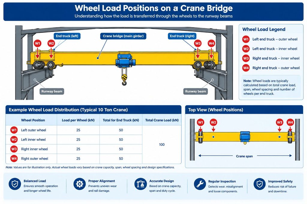
Vertical wheel loads are the loads applied to each crane wheel by the crane. They include the lifted load, the weight of the trolley and the weight of the hoist and the self-weight of the bridge. The greatest wheel load is when the trolley is at its closest to one of the runways and is carrying the full rated load.
- Lateral Loads from Trolley Travel
The lateral loads are those loads that are caused by the motion of the trolley across the bridge and the motion of the crane through the creation of side loads. These forces are horizontal on the runway beams and exert a force to the side of the frame. The lateral loads are typically quoted as a percentage of the lifted load and the trolley weight and are dependent on the governing standard and crane duty class.
- Longitudinal Loads from Bridge Travel
Longitudinal loads are forces experienced on the runway during bridge starting, stopping, and travel. This is primarily due to braking forces. These loads are passed to the building via the crane stops, end trucks, and bracing; therefore, the connections and bracing around the crane bay need to be able to support these loads.
- Impact and Dynamic Effects
Dynamic effects come about when loads are being lifted and lowered, which increases the static load on the wheels. Designers use an impact factor (typically about 25 percent for typical cab-operated and pendant-operated cranes) applied to the vertical load, as prescribed by the governing code. Failure to consider dynamic effects could result in undersized runway beams and connections.
How are crane wheel loads calculated?
The order of wheel load calculation is consistent. The order of working helps to minimise errors and facilitates examination of the design.
- Verify the crane’s rating, class, and span.
- Get the manufacturer’s information such as the weight of the bridge, weight of the trolley, wheel base, and minimum hook approach.
- The maximum wheel load is determined by positioning the trolley at its closest position to the runway and the rated load.
- Find the smallest load on each wheel when the trolley is as far out as possible with no load lifted.
- Use the impact factor for the vertical wheel loads.
- Determine forces acting in the lateral and longitudinal directions as per the governing standard.
- Calculate load factors and add up the loads from the crane to other loads.
- Inspect each combination for the runway beam, columns, bracing, connections and foundation.
The table below gives a summary of the main load components and their usual location of consideration.
| Load Component | Source | Where It Is Checked |
| Maximum vertical wheel load | Rated load plus trolley, hoist, and bridge weight | Runway beam, column, base plate |
| Minimum vertical wheel load | Crane self-weight with no lifted load | Stability and uplift checks |
| Lateral load | Trolley travel and crane motion | Runway beam, bracing, columns |
| Longitudinal load | Bridge braking and acceleration | Bracing, stops, end connections |
| Impact factor | Dynamic lifting effects | Vertical wheel load amplification |
Which design standards apply to crane loads in Australia?
Typical Australian projects refer to loading, steel design, and crane-specific standards. The table below shows the most common references and their roles. Always check with the relevant authority for current editions and any project-specific requirements.
| Standard | Scope | Role in Crane Load Design |
| AS 1170.1 | General design actions | Defines permanent, imposed, and other general loads |
| AS 4100 | Steel structures | Governs member strength, stability, and connection design |
| AS 1418 series | Cranes, hoists, and winches | Provides crane-specific requirements and classifications |
| MBMA Metal Building Systems Manual | Metal building practice | Often referenced for PEB-specific detailing practice |
It is also important for the designer to review the crane manufacturer’s data and any client requirements. When standards are not agreed upon, or conflict, the engineer of record for the project decides.
How are crane runway beams designed?
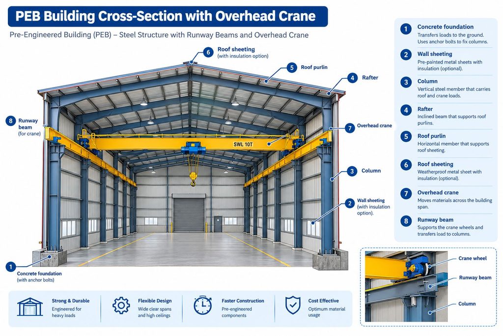
The crane wheels run on the beams, and the load is carried from the crane to the columns. They need to be bent in the vertical plane and side to side and resist the torsional forces caused by the eccentric wheel loads, as well as fatigue loads from repeated crane movements.
A variety of brackets or corbels can be attached to the columns to hold the runway beams up in PEB projects. Eccentric connections generate extra moments, and this is because of the bracket geometry. Serviceability is also of importance, since a high deflection may lead to problems in crane handling and to visible movement in the bay.
Moreover, the lateral stability of the top flange should be addressed, especially at the end of the runway beam where the roof system is not providing lateral stability. A continuous top-flange restraint or lateral bracing is sometimes necessary. For cranes of higher duty classes, fatigue analysis is worthy of consideration, as it can be a source of cracks developing at welded details over time.
How should connections and bracing handle crane forces?
The crane loads are transferred to the main frame and foundations via connections and bracing. Bolted and welded connections between the bracket and runway beam, and between the runway beam and the column, should withstand the combined forces of vertical, lateral, and longitudinal loads.
The crane near bracing is typically heavier than other parts of the building. Longitudinal bracing helps to resist the braking forces applied to the bridge, and horizontal bracing at the runway level will distribute lateral loads. The load path from the crane to the foundation is typically inspected by engineers to ensure that no connection is missed.
3D modelling is generally used by detailers providing structural steel detailing services in Australia. This assists in the recognition of conflicts of bracing, service penetrations, and crane stops prior to the beginning of fabrication.
Why does detailing matter for crane systems?
Without the detail, a correct design will not work. The crane systems are composed of many small parts such as Stiffeners, Cleats, Stops, Rail Clips, and Bolt Groups. All of them can be sources of delay if information is missing or incomplete.
Good detailing verifies member dimensions, bolt details, weld types, tolerances and erection sequences. It also synchronises the crane bay with the overall building, allowing roof purlins, wall girts and services to not interfere with the runway system.
When it comes to complex industrial projects and the need for experienced support, many project teams look for structural steel detailing services in Australia. Crane system knowledge by the detailer will minimize inquiries for fabrication and erection.
Therefore, shop drawings services in Australia are particularly crucial on crane projects. A shop drawing gives exact dimensions of members, hole locations, weld symbols, and the orientation of brackets. They are used by fabricators to make accurate parts, and if there is a mismatch, it can impact the alignment of the crane when it’s on site.
How do fabrication and erection drawings support crane systems?
Fabrication drawings are used to convey the design to the workshop. They explain the cutting, drilling, welding, and finishing of each piece. Accurate drawings of the fabricated crane products are essential to the manufacture of runway beams, which are required to be straight and aligned within close tolerances.
Erection drawings instruct the site team on assembly. They provide the sequence of columns, brackets, runway beams and bracing, bolt torque values and temporary bracing. Erection drawings also can be used by the crew to verify that the crane rails have the correct gauge and elevation before the crane is put in use.
When it comes to industrial steel projects, there is a wide variety of cases where many fabricators and contractors will seek out steel fabrication drawings services in Australia that have the potential to provide them with clear documentation that they can use to build their projects. The same goes for erection drawings services in Australia that assist the site teams to install crane systems correctly and safely. The documents should be read in conjunction with each other to ensure that fabrication and erection instructions correspond.
What are the most common crane load design mistakes?
Some common errors can be found in PEB projects. Early recognition of their occurrence saves time and money.
- Using crane data from another model or capacity than that finally provided
- Failure to consider the effect of the vertical wheel loads or use the wrong effect.
- Deleting the longitudinal braking forces from the bracing design
- Not checking the minimum wheel load for uplift and stability.
- Assuming that the restraint details are known and that the lateral stability of the runway beam is assumed without checking.
- Creating incomplete steel fabrication drawings services in Australia that do not provide enough information about the geometry of the brackets or the welds.
- Providing erection drawings services in Australia, prior to the final crane data being confirmed.
These are all problems that may result in redesign or rework. The risk is greatly lowered when the crane supplier, the engineer and the detailer are in constant communication.
Conclusion
It is necessary to pay attention to the load types, calculation procedures, and standards during the design of PEB loads. If the crane forces are calculated early, the building can be designed efficiently, with no extra steel. Strong connections, well-designed bracing, and accurate runway beams ensure that, over time, the crane will always be safe and reliable.
Communication is essential between the engineer, crane supplier, and detailer for success. Quality structural steel detailing services in Australia benefit the project schedule and budget and ensure that each member of the team delivers the structure as required.
Frequently asked questions
PEB buildings typically have overhead cranes between 5 and 20 tonnes, but larger capacities may be required depending on the specific application.
Yes, cranes generally have to be larger columns, rafters, and runway beams, and a crane will typically need extra bracing.
The designers are generally referring to AS 1170.1 for general actions, AS 4100 for steel design, and the AS 1418 series for cranes.
Shop drawings provide precise member dimensions, connections, and bracket positioning, ensuring accurate and safe installation of runway systems.